
Pinch roller device

A pinch roll and roll body technology, applied in the field of shearing equipment, can solve the problems of steel plate deviation, steel plate misalignment, and reduce the quality of steel plate shearing, and achieve the effect of increasing labor intensity

Active Publication Date: 2022-03-18
CHINA ERZHONG GRP DEYANG HEAVY IND
View PDF16 Cites 0 Cited by
  • Summary
  • Abstract
  • Description
  • Claims
  • Application Information

AI Technical Summary

Problems solved by technology

However, in the process of conveying the steel plate, the traditional pinch roller device often has the phenomenon of deviation of the steel plate, which in turn causes the wrong side of the steel plate during the shearing process, which reduces the shearing quality of the steel plate
The misalignment of the steel plate not only needs manual repair, which increases the labor intensity of the workers, but also the steel plate with serious misalignment will be re-cut or scrapped, which reduces the production efficiency of the equipment and the yield of the steel plate

Method used


Image

  • Pinch roller device
  • Pinch roller device
  • Pinch roller device

Examples


Embodiment approach

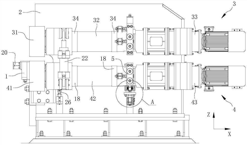
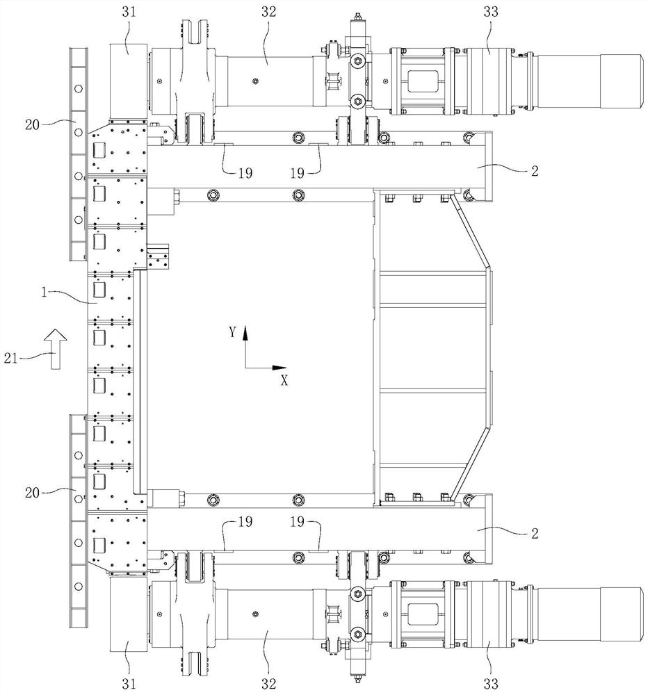
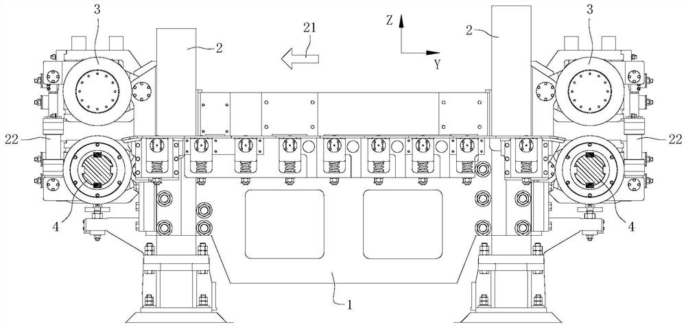
[0045] As an embodiment, the elastic device is a compression spring 14 , the upper end of the compression spring 14 abuts against the bottom of the lower pinch roller body 42 , and the lower end of the compression spring 14 abuts against the bottom of the installation hole 12 . As another embodiment, the elastic device includes a top plate 13 abutting against the bottom of the lower pinch roller body 42 , and a compression spring 14 arranged under the top plate 13 . The top plate 13 can move up and down in the installation hole 12 , and under the action of the compression spring 14 , the top plate 13 abuts and cooperates with the bottom of the lower pinch roller body 42 . By setting the top plate 13 , the pressure of the compression spring 14 on the bottom of the lower pinch roller body 42 can be dispersed to prevent the bottom of the lower pinch roller body 42 from being scratched by the compression spring 14 . Preferably, the bottom of the top plate 13 has a guide rod 15 ext...


PUM


Abstract

The present invention relates to the technical field of shearing equipment, and provides a pinch roller device, which includes a lower knife rest, a frame, an upper pinch roller assembly and a lower pinch roller assembly; it also includes a connecting frame, a frame boss, Jacking screw, connecting flange and the first connecting mechanism; the connecting frame is connected to the rear end of the lower pinch roller body; the frame boss is arranged below the connecting frame and connected to the frame; the lower end of the jacking screw is The threaded connection is fixed on the boss of the frame, and the upper end of the top screw abuts against the bottom of the connecting frame; the connecting flange is installed on the top screw and connected with the connecting frame through the first connecting mechanism. By arranging the first fixing device, the rear end of the lower pinch roller body is fixedly connected with the machine frame, so that in the process of pressurizing and pinching the steel plate, the phenomenon of the head and tail of the lower pinch roller is eliminated. The levelness of the lower pinch roller is guaranteed, and the pinch force is prevented from forming a torque on the steel plate when the steel plate is conveyed, causing the steel plate to deviate.

Description

technical field [0001] The invention relates to the technical field of shearing equipment, in particular to a pinch roller device. Background technique [0002] The pinch roller device on the double shear body plays a vital role when the roll-cut double shear shears the steel plate. The function of the pinch roller device in the double shear is to clamp the sheared steel plate and convey the Or sheared steel plate, to ensure the shear requirements of the edge of the steel plate. However, in the process of conveying the steel plate with the traditional pinch roller device, the phenomenon of deviation of the steel plate often occurs, which in turn causes the wrong edge of the steel plate during the shearing process, and reduces the shearing quality of the steel plate. The misalignment of the steel plate not only needs manual repair, which increases the labor intensity of the workers, but also the steel plate with serious misalignment will be re-cut or scrapped, which reduces ...

Claims


Application Information

Patent Timeline
Patent Type & Authority Patents(China)
IPC IPC(8): B23D33/00B23D33/02
CPCB23D33/02B23D33/00
Inventor 陈伦树
Owner CHINA ERZHONG GRP DEYANG HEAVY IND
Learn More