Unlock instant, AI-driven research and patent intelligence for your innovation.

Force storage device

A technology of power storage and power storage spring, which is applied in the field of feeder equipment, can solve the problems of many parts, large volume, and inapplicability, and achieve the effect of few parts and small volume

Inactive Publication Date: 2021-04-27
HANGZHOU MEISHIMEIKE IOT TECH CO
View PDF0 Cites 0 Cited by
  • Summary
  • Abstract
  • Description
  • Claims
  • Application Information

AI Technical Summary

Problems solved by technology

[0002] At present, the known power storage devices have spring power storage, including springs, tension and compression springs, leaf springs, etc., but generally springs will have a maximum power storage state. When the spring is close to the maximum power storage deformation state, it will be unable to store power. , or even damage the spring, in the prior art, although there are already slipping devices installed on the spring, they are generally aimed at small machines, and cannot be applied to large and medium-sized spring power storage devices, which has also caused the current large and medium-sized spring storage devices. The force device has large volume, many parts, high price, high failure rate, etc.

Method used


Image

  • Force storage device
  • Force storage device
  • Force storage device

Examples


Embodiment Construction

[0016] The present invention will be further described below in conjunction with specific examples, but the present invention is not limited to these specific implementations. Those skilled in the art will realize that the present invention covers all alternatives, modifications and equivalents as may be included within the scope of the claims.

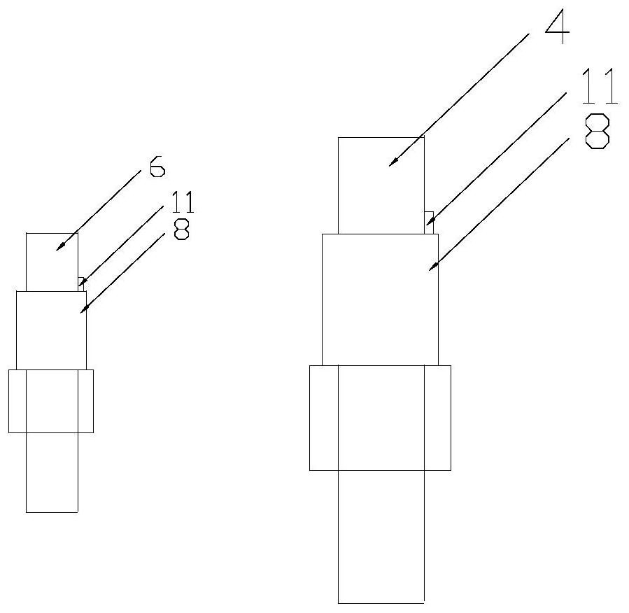
[0017] Such as Figure 1-3 As shown, a power storage device is shown, including a fixed bracket 1, a support plate 2, a connecting plate 3, a driving shaft 4, a driving gear 5, a driven shaft 6, a driven gear 7, a power storage spring 8, and an eccentric wheel 9 and guide wheels 10, the support plate 2 is arranged on the fixed bracket 1, and is perpendicular to the fixed bracket 1, and the driving shaft 4 and the driven shaft 6 are arranged on the fixed bracket 1, so The driving gear 5 and the driven gear 7 mesh with each other and are correspondingly arranged on the driving shaft 4 and the driven shaft 6, and the driving shaft 4 and...


PUM


Abstract

The invention relates to a force storage device. The device comprises a fixing support, a supporting plate, a connecting plate, a driving shaft, a driving gear, a driven shaft, a driven gear, force storage springs, an eccentric wheel and a guide wheel. The supporting plate is arranged on the fixing support and is perpendicular to the fixing support, and the driving shaft and the driven shaft are arranged on the fixing support. The driving gear and the driven gear are meshed with each other and correspondingly arranged on the driving shaft and the driven shaft, the driving shaft and the driven shaft are sleeved with the force storage springs respectively, and the connecting plate is arranged between the top of the supporting plate and the upper end of the inner side of a vertical panel of the fixing support. The guide wheel is arranged on the vertical panel of the fixing support. The invention aims at providing a heat exchange chamber for coal forming, and compared with an existing force storage device, the device is smaller in size, relatively few in parts, free of damage caused by too large storage force and suitable for wide application and popularization.

Description

technical field [0001] The invention relates to the field of feeder equipment, in particular to a power storage device. Background technique [0002] At present, the known power storage devices have spring power storage, including springs, tension and compression springs, leaf springs, etc., but generally springs will have a maximum power storage state. When the spring is close to the maximum power storage deformation state, it will appear unable to store power. , or even damage the spring, in the prior art, although a slipping device has been installed on the spring, it is generally aimed at small machines, and it is not applicable to large and medium-sized spring power storage devices, which has also caused the current large and medium-sized spring storage device The power device is large in size, many parts, expensive, and has a high failure rate. Contents of the invention [0003] In order to overcome the shortcomings in the prior art, the object of the present invent...

Claims


Application Information

Patent Timeline
IPC IPC(8): F16H37/12F03G1/00F03G1/06
CPCF03G1/00F03G1/06F16H37/12
Inventor 朱团团
Owner HANGZHOU MEISHIMEIKE IOT TECH CO