
Dynamic decorative frame for solving solar focusing and modeling limitations

A limited and decorative frame technology, applied in the field of dynamic decorative frames, can solve the problems of not being able to block the light-emitting surface of the lens, failing to meet lighting requirements, and increasing the risk of sun focusing

Pending Publication Date: 2021-04-27
HELLA BHAPSANHEAUTOMOTIVE LIGHTING CO LTD
View PDF1 Cites 0 Cited by
  • Summary
  • Abstract
  • Description
  • Claims
  • Application Information

AI Technical Summary

Problems solved by technology

[0003] Patent CN201910261446.2 discloses a headlight lens module, which aims at the problem of low lumen value of LEDs in the prior art. Car lights are mainly used in signal lamps such as turn signals and brake lights, which cannot meet the lighting requirements of car headlights. By using 2n LED lamp beads as the light source, it has the advantages of LED itself (strong reliability, On the basis of long service life, high color purity, and fast response speed), the lumen value is increased by increasing the number of lamp beads to meet the lighting requirements, and the arrangement of multiple LED lamp beads in branches expands the viewing angle and improves driving safety
[0004] The above-mentioned dynamic decorative frame has some shortcomings: the decorative frame at the front of the module lens cannot block the light-emitting surface of the lens, resulting in a large opening in the Z direction of the lens shape, and the shape design is limited , the optical opening of the module lens is not blocked, the risk of focusing the sun increases, and the static decorative frame lacks a sense of technology

Method used


Image

  • Dynamic decorative frame for solving solar focusing and modeling limitations

Examples


Embodiment Construction

[0016] In order to make the purpose, technical solutions and advantages of the present invention clearer, the present invention will be further described in detail below in conjunction with the accompanying drawings. Obviously, the described embodiments are only some of the embodiments of the present invention, rather than all of them. Based on the embodiments of the present invention, all other embodiments obtained by persons of ordinary skill in the art without making creative efforts belong to the protection scope of the present invention.

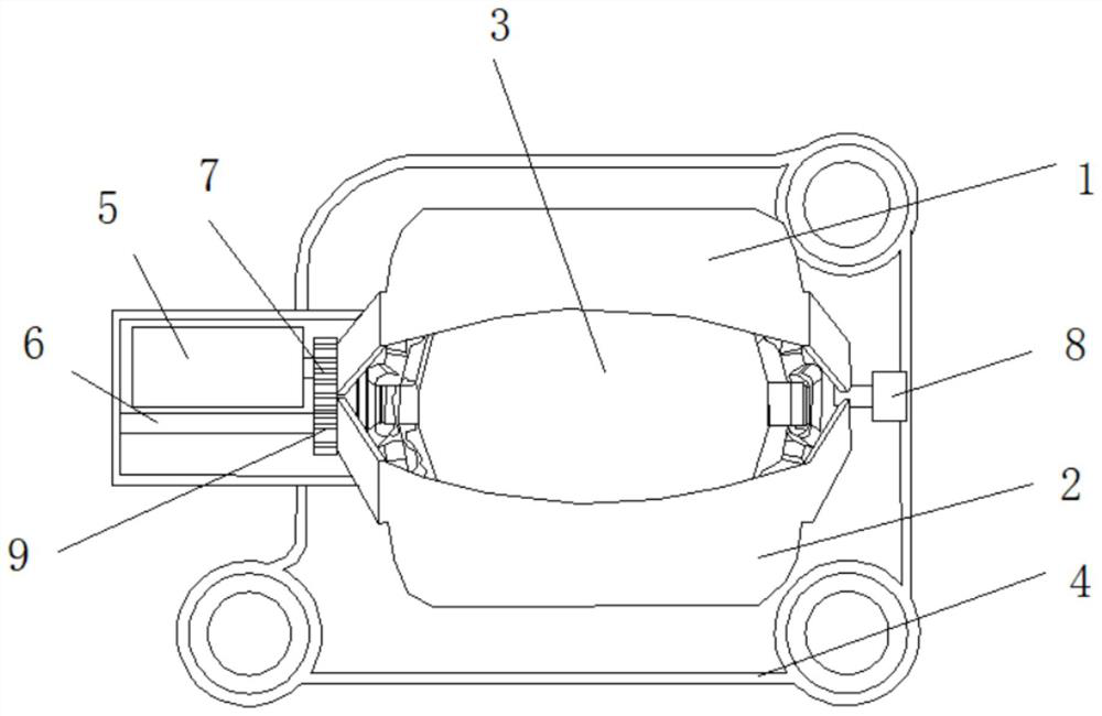
[0017] The following will combine figure 1 A dynamic decorative frame that solves the limitations of the sun's focus and shape according to the embodiment of the present invention will be described in detail.

[0018] refer to figure 1 As shown, a dynamic decorative frame that solves the limitations of solar focusing and modeling provided by the embodiment of the present invention includes a module bracket 4, and an optical module 3 is...


PUM


Abstract

The invention discloses a dynamic decorative frame for solving solar focusing and modeling limitations, and belongs to the field of automobile equipment. Thedynamic decorative frame comprises a module bracket, a light module is fixedly mounted in the center of the module bracket, a transmission gear A is rotationally mounted at the upper end of the left side of the light module, and an electromagnetic valve is rotationally connected to the left end of the transmission gear A; a transmission gear B is rotationally installed at the lower end of the left side of the light module, a transmission gear shaft is rotationally installed at the left end of the transmission gear B, a decorative frame A is rotationally installed on the right side of the transmission gear A, a decorative frame B is rotationally installed on the right side of the transmission gear B, and rotating shafts are connected to the right sides of the decorative frame A and the decorative frame B. By arranging a meshing structure and a novel structure, the practicability of the dynamic decorative frame is improved.

Description

technical field [0001] The invention relates to the technical field of automobile equipment, in particular to a dynamic decorative frame that solves the limitations of solar focus and shape. Background technique [0002] As an essential safety component for automobile driving, automobile lamps play an important role in the active safety of automobiles. [0003] Patent CN201910261446.2 discloses a headlight lens module. This module is aimed at the low lumen value of LEDs. In the prior art, LED lights are mainly used in signal lamps such as turn signals and brake lights. , can not meet the lighting requirements of the headlights of the car headlights. By selecting 2n LED lamp beads as the light source, it has the advantages of LED itself (strong reliability, long service life, high color purity, and fast response) on the basis of , by increasing the number of lamp beads to increase the lumen value to meet the lighting requirements, and through the arrangement of multiple LED ...

Claims


Application Information

Patent Timeline
IPC IPC(8): F21S41/50F21S43/50B60Q1/04F21W107/10
CPCB60Q1/04F21S41/50F21S43/50F21W2107/10
Inventor 汪思范春州
Owner HELLA BHAPSANHEAUTOMOTIVE LIGHTING CO LTD
Learn More