
Backlight module and liquid crystal display device

A technology for a liquid crystal display device and a backlight module, which is applied to lighting devices, fixed lighting devices, components of lighting devices, etc. The probability of light leakage, the effect of improving the light leakage problem

Inactive Publication Date: 2012-10-24
SHENZHEN CHINA STAR OPTOELECTRONICS TECH CO LTD
View PDF8 Cites 20 Cited by
  • Summary
  • Abstract
  • Description
  • Claims
  • Application Information

AI Technical Summary

Problems solved by technology

[0007] The technical problem mainly solved by the present invention is to provide a backlight module and a liquid crystal display device, so as to improve the problem of uneven distribution of brightness and darkness on the light incident side of the backlight module.

Method used


Image

  • Backlight module and liquid crystal display device
  • Backlight module and liquid crystal display device
  • Backlight module and liquid crystal display device

Examples


Embodiment Construction

[0027] The present invention will be described in detail below in conjunction with the accompanying drawings and embodiments.

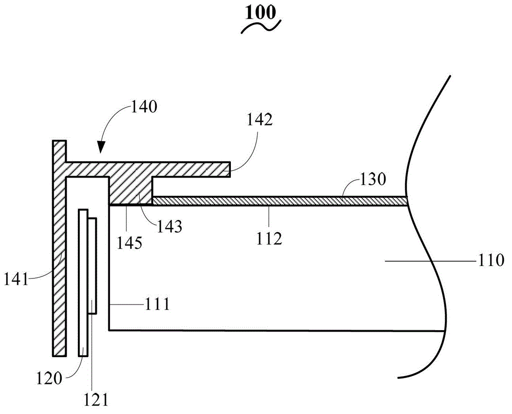
[0028] figure 1 It is a schematic cross-sectional structure diagram of the backlight module of the present invention. Such as figure 1 As shown, the backlight module 100 includes: a light guide plate 110 , a light bar 120 , an optical film 130 and a plastic frame 140 .

[0029] Wherein, the light guide plate 110 includes a light incident surface 111 and a light exit surface 112 connected to the light incident surface 111, the light bar 120 is arranged on one side of the light incident surface 111, and the light bar 120 is arranged at intervals near the light incident surface 111 There are multiple LED light sources 121 , and the optical film 130 is disposed on the light emitting surface 112 .

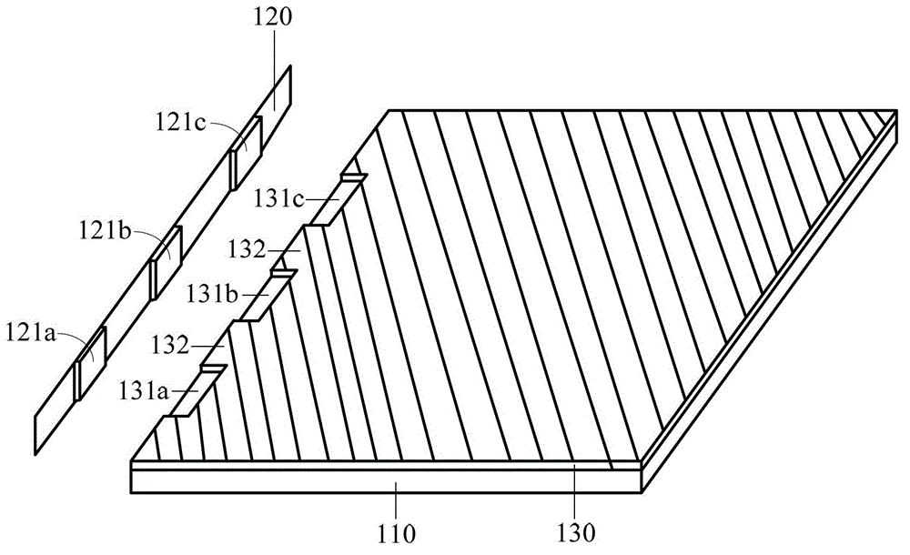
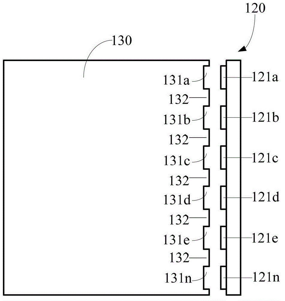
[0030] figure 2 It is a schematic diagram of the corresponding arrangement of the optical film 130 and the light bar 120 in the present invention, image...


PUM


Abstract

The invention provides a backlight module and a liquid crystal display device. The backlight module comprises a light guide plate, a light bar and an optical membrane, wherein the light guide plate comprises a light-in surface and a light-out surface connected with the light-in surface; the light bar is arranged on one side of the light-in surface; multiple LED light sources are spaced on the side of the light bar close to the light-in surface; the optical membrane is arranged on the light-out surface; multiple notches are arranged on the side of the optical membrane close to the light bar; and the multiple notches are in one-to-one correspondence with the multiple LED light sources. In the invention, by use of the optical membrane subjected to shape cutting according to the arrangement of the LED light sources, the problem of non-uniform brightness distribution on the light-in side of the backlight module is solved, the quality of the backlight module is improved, and the problem of light leak of the backlight module due to the narrow frame is solved.

Description

technical field [0001] The invention relates to the field of display technology, in particular to a backlight module and a liquid crystal display device. Background technique [0002] The structure of the existing liquid crystal display device mainly includes a backlight module, a liquid crystal panel and a front frame. Among them, the backlight module is composed of LED light source, light guide plate, optical film, plastic frame, back plate and so on. With the improvement of the efficiency of the LED light source, in order to reduce the cost, the number of LED light sources will gradually decrease, and in this case, the distance between the LED light sources will increase. [0003] At the same time, since the LED light source emits light as a point light source, the LED light source on the light bar does not emit light continuously. Mix the light evenly. Moreover, with the development of LED backlights, it is necessary to further reduce the light mixing distance of LED ...

Claims


Application Information

Patent Timeline
Patent Type & Authority Applications(China)
IPC IPC(8): F21S8/00F21V5/00F21V17/10G02F1/13357F21Y101/02
CPCG02B6/009G02B6/0068G02B6/0088G02B6/0073G02B6/002G02B6/0091G02B6/0021
Inventor 胡哲彰贺虎
Owner SHENZHEN CHINA STAR OPTOELECTRONICS TECH CO LTD
Learn More