Portable microscopic imaging device

An imaging device and microscopic technology, applied in microscopes, image communication, television, etc., can solve the problems of uneven imaging, high proportion, large overall structure, etc., and achieve the effects of uniform imaging, reduced volume, and reduced volume

Active Publication Date: 2019-03-01
CONVERGENCE TECH CO LTD
View PDF4 Cites 5 Cited by
  • Summary
  • Abstract
  • Description
  • Claims
  • Application Information

AI Technical Summary

Problems solved by technology

Miniaturized portable digital microscopes and mobile phone microscopes used with mobile phones solve the problem of portability of microscopes, but there are still some limitations, such as the need for external light sources for lighting. When the lighting and the microscope body are combined, Also needs to contain the battery, resulting in a larger overall structure
Although the applicant's prior patent CN108681188A proposed a certain improvement plan, it was found in actual use that the structure of the light guide reflection end and the lens mounting hole was adopted. Part of the illumination light at the mounting hole is inevitably directly irradiated into the lens, and the proportion is relatively high, instead of being reflected into the lens by the microscopic object, resulting in uneven imaging, and the imaging quality needs to be improved; in addition, the detachable lens body The installation method needs to be further improved for models where the lens protrudes from the phone body.

Method used


Image

  • Portable microscopic imaging device
  • Portable microscopic imaging device
  • Portable microscopic imaging device

Examples


Embodiment Construction

[0038] In order to make the object, technical solution and advantages of the present invention clearer, the present invention will be further described in detail below in conjunction with the accompanying drawings and embodiments. It should be understood that the specific embodiments described here are only used to explain the present invention, not to limit the present invention. In addition, the technical features involved in the various embodiments of the present invention described below can be combined with each other as long as they do not constitute a conflict with each other. The present invention will be further described in detail below in combination with specific embodiments.

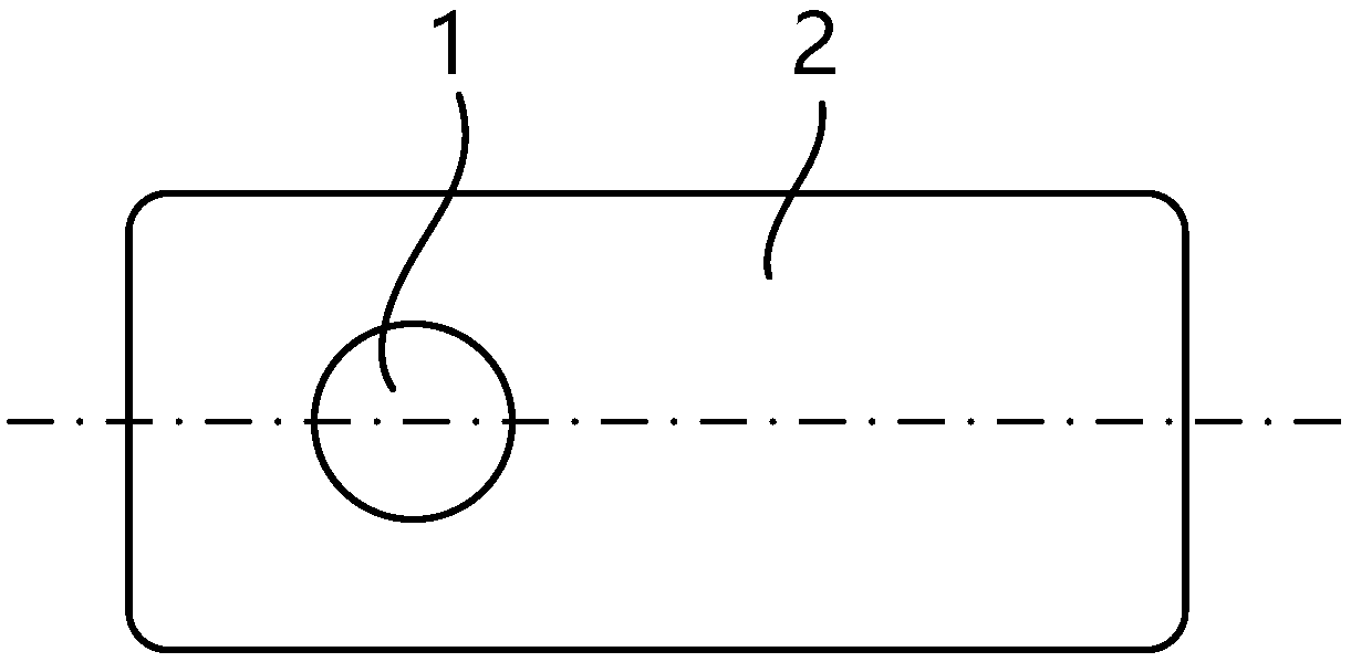
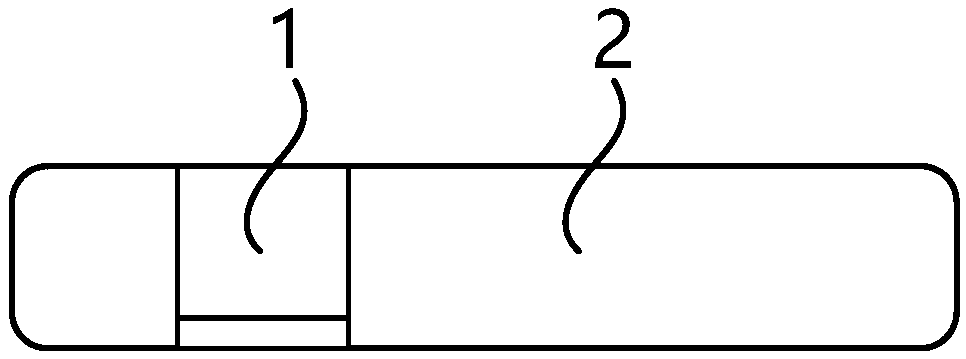
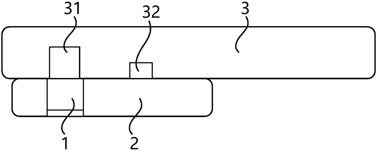
[0039] like Figure 1-3 As shown, a portable microscopic imaging device of the present invention is detachably connected to a portable imaging device 3 having a camera 31 and an illuminator 32, such as a mobile phone, a tablet, etc. device 32, and the illuminator 32 is, for example, a flas...


PUM


Abstract

The invention discloses a portable microscopic imaging device, which is detachably connected to portable imaging equipment (3) with a camera (31) and an illuminator (32). The portable microscopic imaging device comprises a lens (1) and a lens body (2), wherein the lens body (2) is made of transparent or semi-transparent solid materials, and the thickness of the lens body in a length direction is even; the outer surface of the front side (20b) of the lens body (2) is locally provided with an independent mirror surface reflection layer or a diffuse reflection layer to cover the illuminator (32);the mirror surface reflection layer or the diffuse reflection layer is made of light-proof materials and forms a sealed annular light transmission ring with the peripheral edge of the front side (20b) of the lens body (2); and the opening size of the mounting hole (21) of the lens body (2) on the front side (20b) of the lens body is greater than the size of the lens (1). Through the re-optimization design of the structure, the imaging device has the advantages of being small, light, convenient, easy in use, high in imaging quality and high in amplification factors.

Description

technical field [0001] The invention belongs to the field of microscopic imaging, in particular to a portable microscopic imaging device. Background technique [0002] A microscope can observe microscopic structures. A traditional microscope consists of an objective lens and an eyepiece, which are used to magnify the microscopic structure and present it to the clear distance of the human eye. Digital microscopes use area array photodetectors instead of human eyes for detection, and can record images into digital image files, which brings convenience to signal acquisition. [0003] Microscopes are usually larger in size, most commonly in the form of a benchtop microscope that sits on a table. Miniaturized portable digital microscopes and mobile phone microscopes used with mobile phones solve the problem of portability of microscopes, but there are still some limitations, such as the need for external light sources for lighting. When the lighting and the microscope body are ...

Claims


Application Information

Patent Timeline
Patent Type & Authority Applications(China)
IPC IPC(8): G03B17/12G03B15/03H04M1/02
CPCH04M1/0264G03B15/03G03B17/12H04M1/0254G03B17/565G03B15/06G03B2215/0575G03B2215/0582G02B21/36G02B21/06G02B21/0008H04N23/55H04N23/51H04N23/57G02B21/0032
Inventor 胡庆磊黄凯李宁李梦婷
Owner CONVERGENCE TECH CO LTD
Why Eureka
Try Eureka