
Bus bridge structure and bus bridge system

A bus bridge and busbar technology, which is applied in busbar/circuit layout, cooling busbar device, fully enclosed busbar device, etc., can solve the problems of deep front and rear extension of commutation copper bars, affecting the normal opening of compartment pressure relief plates, etc. Normal pressure relief effect

Pending Publication Date: 2021-04-27
HUAYI ELECTRIC CO LTD
View PDF1 Cites 0 Cited by
  • Summary
  • Abstract
  • Description
  • Claims
  • Application Information

AI Technical Summary

Problems solved by technology

The busbar bridge includes a vertical bridge body located in the lower casing of the commutation phase. In the vertical bridge body, the commutation is realized by connecting the same-phase busbars on both sides through the commutation copper bar. In order to ensure a sufficient safety distance in the vertical bridge body, the commutation The phase copper bar needs to be extended for a certain distance away from one side of the bus bar, and then bent towards the same phase bus bar on the other side. The depth of the vertical bridge body is deeper than that before the commutation, and the excess part of the vertical bridge body is in contact with the pressure relief plate on the top of other compartments of the switchgear, which will affect the normal opening of the pressure relief plate in this compartment

Method used


Image

  • Bus bridge structure and bus bridge system
  • Bus bridge structure and bus bridge system
  • Bus bridge structure and bus bridge system

Examples


Embodiment 1

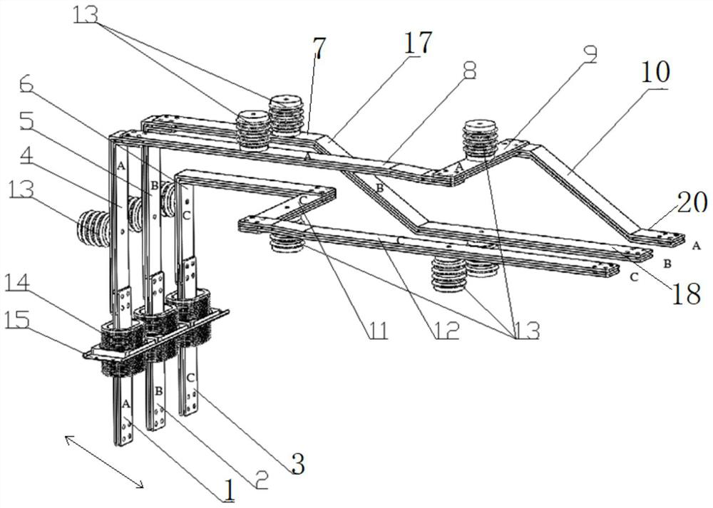
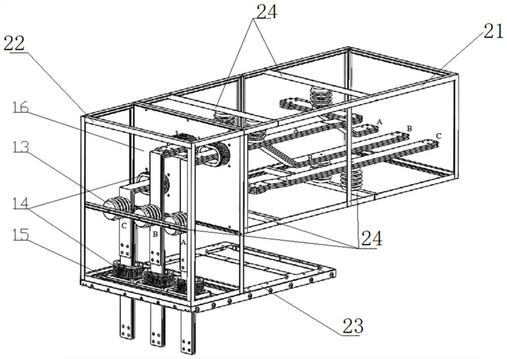
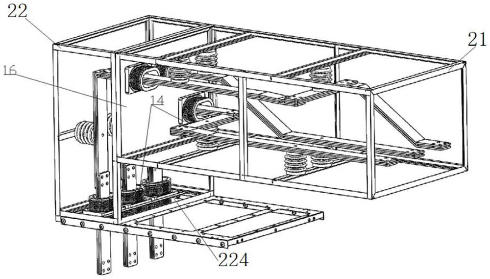
[0042] This embodiment provides a bus bridge structure, such as Figure 1 to Figure 4 As shown, it includes a vertical bridge body and a horizontal bridge body.

[0043] Among them, the vertical bridge body includes A-phase lead-out bar 1, B-phase lead-out bar 2, C-phase lead-out bar 3, and A-phase lead-out bar 1 connected to phase A Corner row 4, B-phase corner row 5 connected to B-phase lead-out row 2, C-phase corner row 6 connected to C-phase lead-out row 3. A-phase lead-out bar 1, B-phase lead-out bar 2, and C-phase lead-out bar 3 are drawn from the inside of the switchgear and extend vertically upward. The A-phase corner row 4, the B-phase corner row 5 and the C-phase corner row 6 all extend vertically upwards and bend horizontally toward the first direction at their respective tops to form a horizontal bending portion; the A-phase corner row 4 and the B-phase corner row The bottoms of the vertical sections of the phase 5 and C-phase corner rows 6 are connected to their c...

Embodiment 2

[0065] This embodiment provides a bus bridge system, which includes the bus bridge structure in Embodiment 1 and switch cabinets arranged at both ends of the bottom of the bus bridge, and the vertical bus bridge box 22 is arranged on the top cover 23 of the switch cabinet. The busbar bridge structure in the busbar bridge system has a small depth along the front and rear directions of the switchgear, which can ensure the normal pressure relief of adjacent switchgear compartments.


PUM


Abstract

The invention provides a bus bridge structure and a bus bridge system. The bus bridge structure comprises a vertical bridge body and a horizontal bridge body, wherein the horizontal bridge body comprises an A-phase adapter bar and a C-phase adapter bar. According to the bus bridge structure, the adapter bars used for commutation are arranged on the horizontal bridge body, in order to ensure a safe distance, the A-phase adapter bars and the C-phase adapter bars are arranged in the horizontal bridge body up and down at intervals, the upper space and the lower space of the horizontal bridge body are occupied during commutation, the horizontal bridge body is located above the vertical bridge body, the bus bars of each phase of the vertical bridge body part vertically extend upwards, and the depth of the vertical bridge body in the front-back direction is small. When the box body surrounds the vertical bridge body, the vertical bridge body is installed above the switch cabinet, the depth of the vertical bridge body is small, the box body base can be completely borne on the top face of the switch cabinet below, the situation that the box body base extends out of the switch cabinet and influences normal opening of other top pressure relief plates of the switch cabinet is avoided, and normal pressure relief of adjacent switch cabinet compartments is guaranteed.

Description

technical field [0001] The invention relates to the technical field of high-voltage switch cabinets, in particular to a bus bridge structure and a bus bridge system. Background technique [0002] The switchgear is limited by the space of the on-site power distribution room, and often needs to be arranged in two or more rows. At this time, if it is necessary to connect the busbars of two or more rows of switch cabinets, it is often necessary to use busbar bridges, power cables or pipe-type Busbar and other schemes for connection. Among them, the connection method of the busbar bridge is the most economical and safe. The phase sequence of the switchgear is based on the requirements of regional or technical agreements. Facing the switchgear, A, B, and C are arranged in order from left to right. When two switchgears are arranged facing each other, if the busbar bridge is directly connected to the two face-to-face switchgears without commutation, the phase sequence of the busba...

Claims


Application Information

Patent Timeline
Patent Type & Authority Applications(China)
IPC IPC(8): H02G5/06H02G5/10H02B1/20H02B1/32H02B1/56H02B13/025
CPCH02B1/207H02B1/32H02B1/565H02B13/025H02G5/06H02G5/10
Inventor 吴亮陈旭敏章纪勇连建勇曾繁国项岳明郑永华刘佰强
Owner HUAYI ELECTRIC CO LTD
Learn More