Gate with flow control mechanism for water conservancy project and method thereof

A technology of flow control and water conservancy engineering, applied in the direction of cleaning methods using tools, water conservancy engineering, sea area engineering, etc., can solve problems such as rope burden, dam collapse, and dam washout, and achieve the effect of avoiding excessive burden

Pending Publication Date: 2022-04-12
亓会中
View PDF0 Cites 0 Cited by
  • Summary
  • Abstract
  • Description
  • Claims
  • Application Information

AI Technical Summary

Problems solved by technology

[0007] The gates used in existing water conservancy projects often need to be half-opened during normal use, so as to adjust the flow rate of water passing through the gates, and avoid excessive flow, which will cause the downstream river beach to be washed away by the flood. During semi-open operation, it often causes a huge burden on the rope connected to the top of the gate, which is easy to shorten the service life of the rope, resulting in the sudden break of the rope during the process of opening the gate for water discharge, causing the gate to fall, and the gate that suddenly fell The dam may be smashed, causing the dam to collapse, flooding the dam and flooding the downstream river

Method used


Image

  • Gate with flow control mechanism for water conservancy project and method thereof
  • Gate with flow control mechanism for water conservancy project and method thereof
  • Gate with flow control mechanism for water conservancy project and method thereof

Examples


Embodiment 1

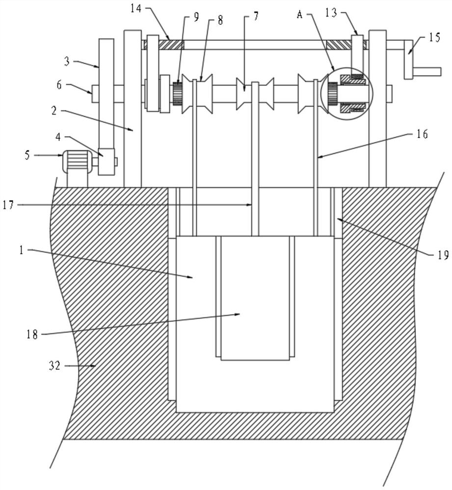
[0038]Please refer to the accompanying drawings, the present invention provides a technical solution: a gate with a flow control mechanism for water conservancy projects, including a main gate 1 and a dam 32, the main gate 1 is slidably connected in the left and right side walls of the dam 32, and the dam 32 Symmetrical support columns 2 are also fixed on the left and right sides above the top surface of the top surface, and the support column 2 is provided with a lifting assembly, the front side of the main gate 1 is provided with a mud pushing assembly, and the main gate 1 is also provided with a grading assembly.

[0039] Wherein, the lifting assembly includes a drive shaft 6 that is rotatably connected between the two support columns 2. The left end of the drive shaft 6 stretches out from the support column 2 and is fixed with a No. 1 gear 3. The left side of the top surface of the dam 32 is provided with a No. 1 motor 5 , No. 2 gear 4 is fixed on the right side driving end...

Embodiment 2

[0047] A gate with a flow control mechanism for water conservancy projects, including a main gate 1 and a dam 32, the main gate 1 is slidingly connected in the left and right side walls of the dam 32, and symmetrical supports are fixed on the left and right sides above the top surface of the dam 32 The column 2 and the support column 2 are provided with a lifting assembly, the front side of the main gate 1 is provided with a mud pushing assembly, and the main gate 1 is also provided with a grading assembly.

[0048] Wherein, the lifting assembly includes a drive shaft 6 that is rotatably connected between the two support columns 2. The left end of the drive shaft 6 stretches out from the support column 2 and is fixed with a No. 1 gear 3. The left side of the top surface of the dam 32 is provided with a No. 1 motor 5 , No. 2 gear 4 is fixed on the right side driving end of No. 1 motor 5, No. 1 gear 3 meshes with No. 2 gear 4, the left and right sides of drive shaft 6 are provide...

Embodiment 3

[0055] A gate with a flow control mechanism for water conservancy projects, including a main gate 1 and a dam 32, the main gate 1 is slidingly connected in the left and right side walls of the dam 32, and symmetrical supports are fixed on the left and right sides above the top surface of the dam 32 The column 2 and the support column 2 are provided with a lifting assembly, the front side of the main gate 1 is provided with a mud pushing assembly, and the main gate 1 is also provided with a grading assembly.

[0056] Wherein, the lifting assembly includes a drive shaft 6 that is rotatably connected between the two support columns 2. The left end of the drive shaft 6 stretches out from the support column 2 and is fixed with a No. 1 gear 3. The left side of the top surface of the dam 32 is provided with a No. 1 motor 5 , No. 2 gear 4 is fixed on the right side driving end of No. 1 motor 5, No. 1 gear 3 meshes with No. 2 gear 4, the left and right sides of drive shaft 6 are provide...


PUM


Abstract

The invention discloses a gate with a flow control mechanism for a water conservancy project and a method thereof in the technical field of water conservancy projects, the gate comprises a main gate and a dam, the main gate is located in the dam, a supporting column is arranged above the dam, a lifting assembly is arranged on the supporting column, a mud pushing assembly is arranged on the front side of the main gate, and a grading assembly is further arranged on the main gate. By arranging the grading assembly, when a worker needs to discharge a small flow, a first motor is started, a second gear and a first gear are in transmission, and due to the fact that the transmission ratio of the second gear and the first gear is large, the first motor can drive a driving shaft to rotate under the condition that the load is small, and therefore a fixed wheel rotates; the second rope is wound, the auxiliary gate is driven to move upwards, a small notch is opened for water drainage, and due to the fact that the reels on the two sides are rotationally connected with the driving shaft, the main gate is fixed, small-flow water drainage is facilitated, and potential safety hazards caused by reduction of the service life due to the fact that the burden of the rope is too large are avoided.

Description

technical field [0001] The invention relates to the technical field of water conservancy engineering, in particular to a gate with a flow control mechanism for water conservancy engineering and a method thereof. Background technique [0002] Water conservancy engineering is a project built to control and allocate natural surface water and groundwater to achieve the purpose of eliminating harm and rejuvenating profits. It is also called water engineering. Water is an indispensable and precious resource for human production and life, but its natural existence The state does not fully meet the needs of human beings. Only by building water conservancy projects can water flow be controlled, floods prevented, and water volume adjusted and distributed to meet the needs of people's life and production for water resources. Water conservancy projects require the construction of dams, dikes, Spillways, sluices, water intakes, channels, raftways, fishways and other types of hydraulic st...

Claims


Application Information

Patent Timeline
IPC IPC(8): E02B7/26E02B7/28E02B7/36B08B1/00B08B1/04
Inventor 亓会中王树
Owner 亓会中
Why Eureka
Try Eureka