
Transformer switching-on impulse current suppression device and method

A technology of inrush current and suppression devices, which is applied in the direction of circuit devices, emergency protection circuit devices, emergency protection circuit devices for limiting overcurrent/overvoltage, etc. Can not meet the use requirements and other problems, to achieve the effect of small circuit changes, reduce the number of switch trips, and reduce the number of trips

Pending Publication Date: 2021-04-27
YONGJI XINSHISU ELECTRIC EQUIP
View PDF3 Cites 0 Cited by
  • Summary
  • Abstract
  • Description
  • Claims
  • Application Information

AI Technical Summary

Problems solved by technology

[0005] 1) This technology can only reduce the inrush current at the moment of transformer closing, but the reduction rate is not very large. In some places where the inrush current needs to be basically eliminated, it cannot meet the use requirements
[0006] 2) This technology generally increases the high-voltage resistance in the high-voltage cabinet at the front end of the transformer and sets it in one of the three-phase voltage circuits. Since it is a high-voltage resistor, there are strict requirements on insulation, which will cause a large increase in the volume of the high-voltage cabinet

Method used


Image

  • Transformer switching-on impulse current suppression device and method

Examples


Embodiment Construction

[0017] At the moment when a transformer with a large capacity (power transformer, rectifier transformer, etc.) is switched on and powered on, due to the transient process inside the transformer, the magnetic flux in the transformer core will increase to twice the normal steady-state value. It is a ferromagnetic material with magnetic saturation characteristics. It is because of this characteristic that the no-load current of the transformer at the moment of switching on increases to 5-20 times of the no-load current.

[0018] Based on the idea of ​​controlling the magnetic flux inside the transformer at the moment of transformer closing, if the magnetic flux at the moment of transformer closing is reduced to slowly rise from zero until the primary side voltage of the transformer reaches the rated voltage, then the transformer escapes the transient state at the moment of closing During the process, the magnetic flux will not increase to twice the steady state, and naturally ther...


PUM


Abstract

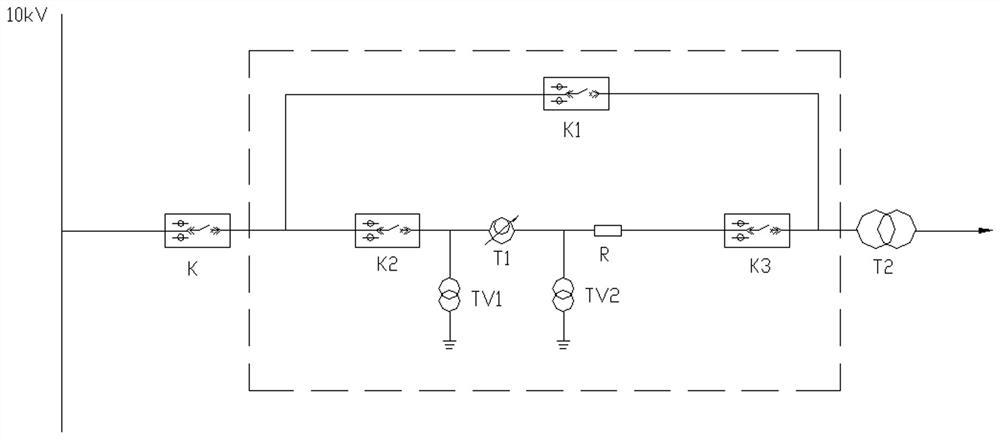
The invention relates to the field of transformer safe operation protection, particularly to a transformer switching-on impulse current suppression device and method, and aims to solve the technical problem that the size of a high-voltage cabinet is increased due to the adoption of a high-voltage resistor because the impact current at the closing moment of an existing transformer is large. The transformer switching-on impulse current suppression device comprises a vacuum circuit breaker K2, a three-way voltage regulator T1, a high-voltage current-limiting resistor R and a vacuum circuit breaker K3 which are sequentially connected in series between a vacuum circuit breaker K and the primary side of a transformer T2, and further comprises a vacuum circuit breaker K1, wherein one end of the K1 is connected to the end, connected with the K, of the K2, and the other end of the K1 is connected with the primary side of the T2. According to the device, the impact current of the transformer at the moment of closing can be greatly reduced to be close to the no-load current value of the transformer, and the influence of the impact current is eliminated; and a transformer loop is slightly changed, a high-voltage cabinet and a transformer do not need to be modified, only cable connection needs to be conducted, and operation is easy.

Description

technical field [0001] The invention relates to the field of transformer safe operation protection, in particular to a transformer closing surge current suppression device and method. Background technique [0002] Large-capacity power transformers, rectifier transformers, and special transformers will generate a large inrush current at the moment of closing. The peak value of the inrush current can reach 5 to 20 times the rated current of the transformer. This current will cause frequent tripping of the front-end switch of the transformer. Especially in large-scale motor test stations and converter test stations, due to the needs of test projects, transformers will be frequently switched on and off, and the impact current of transformers has a greater impact on test work. [0003] In the prior art, a high-voltage resistor is connected in series at the front end of the transformer, and the resistor is used to accelerate the attenuation time of the surge current of the transfo...

Claims


Application Information

Patent Timeline
IPC IPC(8): H02H7/04H02H9/02H02J3/00
CPCH02J3/00H02H9/02H02H7/04
Inventor 赵义波史永双唐泽容郭丽君鲍向斌
Owner YONGJI XINSHISU ELECTRIC EQUIP
Learn More