Verticality detection device for constructional engineering construction

A technology of construction engineering and detection devices, which is applied in the directions of measuring devices, construction, surveying and navigation, etc., can solve the problems of affecting measurement results, inconvenient use, and influence of placement position, and achieve the effect of ensuring accuracy, convenient use, and convenient removal

Pending Publication Date: 2021-04-30
刘金月
View PDF6 Cites 2 Cited by
  • Summary
  • Abstract
  • Description
  • Claims
  • Application Information

AI Technical Summary

Problems solved by technology

[0004] The purpose of the present invention is: in order to solve the problem of measuring the verticality of the wall body in existing construction projects, it is generally possible to use a right-angle measuring ruler to measure, but the size of the existing right-angle measuring ruler is limited, and it is impossible to measure the verticality of the wall at a higher height. The measurement of the wall brings some inconvenience to people's use. At the same time, the use of a right-angle measuring ruler generally needs to be measured at the root of the wall, but generally a large amount of dust will accumulate at the root of the wall, and the dust will affect the placement of the right-angle measuring ruler. In this way It may cause the deviation of the rectangular measuring ruler and affect the measurement results, and a verticality detection device for construction engineering is proposed

Method used


Image

  • Verticality detection device for constructional engineering construction
  • Verticality detection device for constructional engineering construction
  • Verticality detection device for constructional engineering construction

Examples


Embodiment Construction

[0035]The following will clearly and completely describe the technical solutions in the embodiments of the present invention with reference to the accompanying drawings in the embodiments of the present invention. Obviously, the described embodiments are only some, not all, embodiments of the present invention. Based on the embodiments of the present invention, all other embodiments obtained by persons of ordinary skill in the art without creative efforts fall within the protection scope of the present invention.

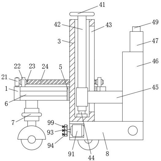
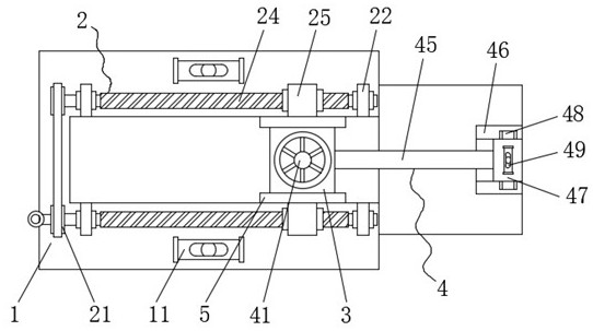
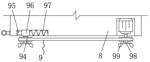
[0036] see Figure 1-6 , the present invention provides a technical solution: a verticality detection device for construction engineering, comprising a support plate 1 and a side plate 3, a through hole is opened on the upper surface of the support plate 1, and a side plate 3 is arranged in the through hole , the front and rear sides of the side plate 3 are provided with an adjustment mechanism 2, the outer surface of the side plate 3 is clamped with a moving block ...


PUM


Abstract

The invention discloses a verticality detection device for constructional engineering construction, which belongs to the technical field of constructional engineering, and comprises a support plate and a side plate, a through hole is formed in the upper surface of the support plate, the side plate is arranged in the through hole, adjusting mechanisms are arranged on the front and rear side surfaces of the side plate, and a moving block is clamped on the outer surface of the side plate. Second sliding blocks are fixedly connected to the front side face and the rear side face of the moving block correspondingly and slidably connected into the second sliding grooves. A detection mechanism is arranged, the right end of a bearing plate is controlled to abut against the wall root, a U-shaped plate and an extension plate are attached to the wall to achieve the effect of detecting the perpendicularity of the wall, and when a higher wall needs to be measured, the second threaded column can be driven to rotate by controlling the hand wheel to rotate, therefore, the second threaded cap can drive the extension plate to move through the connecting plate, at the moment, the overall length of the extension plate and the U-shaped plate is larger, a higher wall can be effectively measured, and convenience is brought to use of people.

Description

technical field [0001] The invention belongs to the technical field of building engineering, and in particular relates to a verticality detection device for building engineering construction. Background technique [0002] A construction project is a part of a construction project, and refers to an engineering entity formed through the construction of various housing buildings and their ancillary facilities and the installation of supporting lines, pipelines, and equipment. Including factories, theaters, hotels, shops, schools, hospitals and residences, etc., to meet people's needs for production, living, learning, and public activities. [0003] In existing construction projects, when measuring the verticality of the wall, it is generally possible to use a right-angle measuring ruler to measure, but the size of the existing right-angle measuring ruler is limited, and it is impossible to measure the wall at a higher height. It is inconvenient to use. At the same time, it is ...

Claims


Application Information

Patent Timeline
IPC IPC(8): G01C9/00G01C9/34G01C15/12E01H15/00
CPCG01C15/12G01C9/34G01C9/00E01H15/00
Inventor 刘金月
Owner 刘金月
Why Eureka
Try Eureka