
A cable tray

A cable tray and side plate technology, applied in the direction of electrical components, etc., can solve problems such as poor use effect, inconvenient disassembly, and difficult maintenance of cables

Active Publication Date: 2021-09-17
江苏庞浙伟环保材料科技有限公司
View PDF7 Cites 0 Cited by
  • Summary
  • Abstract
  • Description
  • Claims
  • Application Information

AI Technical Summary

Problems solved by technology

[0004] The purpose of the present invention is to provide a cable bridge, which aims to solve the technical problems of the integrated structure of the traditional cable bridge in the prior art, which takes up a lot of space, is inconvenient to disassemble, difficult to maintain cables, and leads to poor use effect

Method used

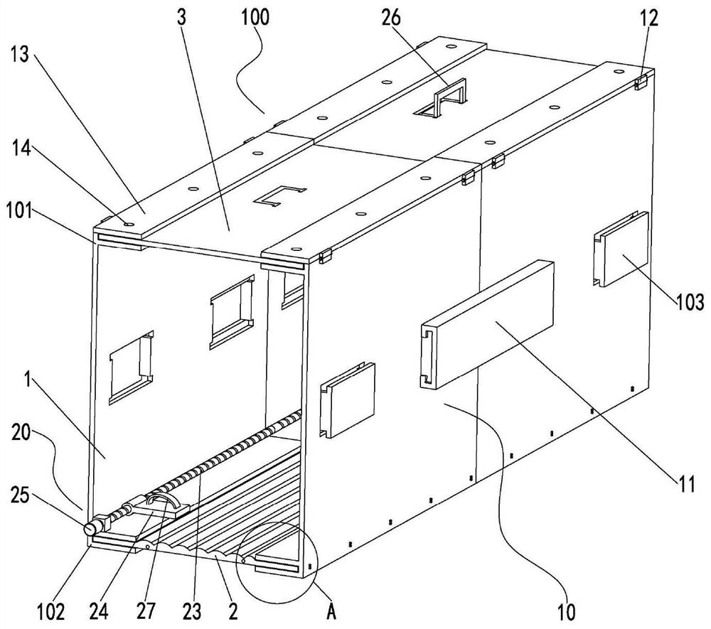
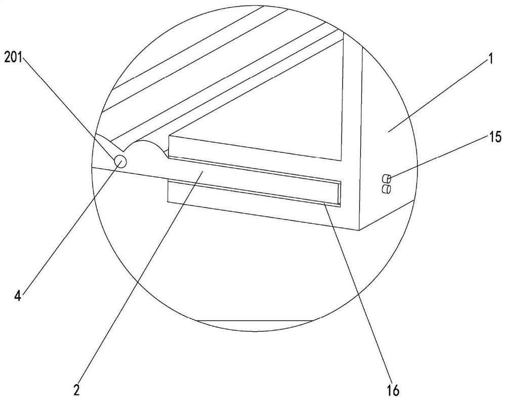
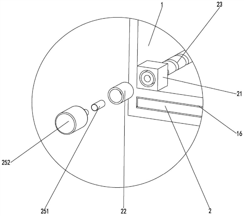

Image

  • A cable tray
  • A cable tray
  • A cable tray

Examples


Embodiment Construction

[0021] Embodiments of the present invention are described in detail below, examples of which are shown in the drawings, wherein the same or similar reference numerals designate the same or similar elements or elements having the same or similar functions throughout. The embodiments described below by referring to the figures are exemplary and are intended to explain the present invention and should not be construed as limiting the present invention.

[0022] In describing the present invention, it should be understood that the terms "length", "width", "upper", "lower", "front", "rear", "left", "right", "vertical", The orientation or positional relationship indicated by "horizontal", "top", "bottom", "inner", "outer", etc. are based on the orientation or positional relationship shown in the drawings, and are only for the convenience of describing the present invention and simplifying the description, rather than Nothing indicating or implying that a referenced device or element...


PUM


Abstract

The invention discloses a cable bridge frame, in which a plurality of the bottom plates are fixed in series through the reinforcing rod penetrating the bottom plate, and the lower extension section of the side plate is vertically engaged on both sides of the bottom plate, and the The fixing screw is fixed to the bottom plate, the cover plate is mounted on the upper extension section, and the hinge clamping mechanism has a clamping force, so that the folding plate is folded and pressed against the cover plate, while the The fixing pin on the folding plate passes through the cover plate, and is engaged and fixed with the upper extension section of the side plate to fix the cover plate, and the fixing plate is snapped into the side plate. On the engaging part, two adjacent side plates are fixed to form the cable bridge for cables to pass through, and the structure can be disassembled, which is convenient for stocking, storage and transportation, and improves storage and transportation efficiency. The cover plate can be removed, which is convenient for disassembly and convenient for cable maintenance.

Description

technical field [0001] The invention relates to the technical field of cable installation, in particular to a cable tray. Background technique [0002] As a common support and protection device for cable laying in the electrical equipment power supply system, the cable tray protects and guides the cables laid in the cable tray. Traditional cable trays are mainly divided into trough, ladder, tray and grid structures. [0003] The traditional cable bridge includes the main body of the bridge and the cover plate welded to the top of the main body of the bridge. Most of them are integral structures, which take up a lot of space during storage and transportation, and are inconvenient to disassemble, difficult to maintain cables, and have poor use effects. Contents of the invention [0004] The purpose of the present invention is to provide a cable bridge, aiming to solve the technical problems of the traditional cable bridge integrated structure in the prior art, which takes u...

Claims


Application Information

Patent Timeline
Patent Type & Authority Patents(China)
IPC IPC(8): H02G3/04H02G3/06
CPCH02G3/0406H02G3/0487H02G3/06
Inventor 庞良伟
Owner 江苏庞浙伟环保材料科技有限公司
Learn More