Internal mixer with dust collection mechanism
A technology of a vacuuming mechanism and an internal mixer, which is applied to the structural parts of electrical equipment, dispersed particle filtration, electrical components, etc., can solve the problems of damage to electronic components, inconvenience to move, and electronic components are easy to cause short circuits, so as to achieve convenient movement. , The effect of time-saving and labor-saving during the moving process
- Summary
- Abstract
- Description
- Claims
- Application Information
AI Technical Summary
Problems solved by technology
Method used
Image
Examples
Embodiment 1
[0028] see figure 1 , figure 2 , image 3 , Figure 4 , Figure 5 , Figure 6 and Figure 8 , the present invention provides a technical solution:
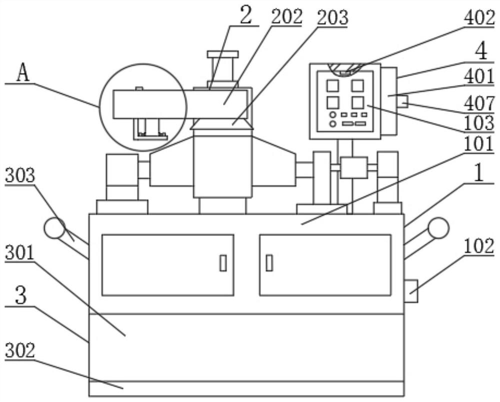
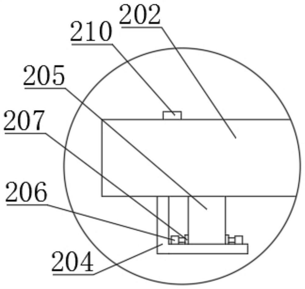
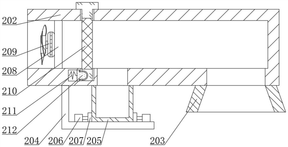
[0029]An internal mixer with a dust suction mechanism, comprising a main body device 1, a dust suction device 2, a moving device 3 and an adjustment device 4, the main body device 1 includes a body 101, a controller 102 and an electric control box 103, the controller 102 and the body 101 is fixedly connected, the electric control box 103 is fixedly connected with the body 101, the dust collection device 2 includes a connecting rod 201, a dust collection box 202, a collection box 205 and a spring 211, the connecting rod 201 is fixedly connected with the body 101, and the dust collection box 202 is connected with the The rod 201 is fixedly connected, the right side of the bottom end surface of the dust collection box 202 is fixedly connected with a dust collection cover 203, the left side of the bottom end surface of the dust...
Embodiment 2
[0033] In embodiment 2, the same part as in embodiment 1 will not be repeated, please refer to the different parts figure 1 , figure 2 , image 3 , Figure 4 , Figure 5 , Figure 6 and Figure 7 , the present invention provides a technical solution:
[0034] An electric heating tube 410 is provided at the inner left end of the top surface of the bellows 407, and the electric heating tube 410 is fixedly connected with the bellows 407. This setting can heat the drawn gas and prevent the electric control box 103 from moisture.
[0035] Work flow: the power supply of all electrical appliances in the device is an external power supply. When the temperature and humidity sensor 402 senses that the humidity inside the electric control box 103 is high, the temperature and humidity sensor 402 controls the rotation of the second fan 409 and The heating tube 410 is energized, and the second fan 409 draws the gas to be heated by the electric heating tube 410 to become hot gas and t...
PUM
 Abstract
Description
Claims
Application Information
 - R&D
- Intellectual Property
- Life Sciences
- Materials
- Tech Scout
- Unparalleled Data Quality
- Higher Quality Content
- 60% Fewer Hallucinations
Browse by: Latest US Patents, China's latest patents, Technical Efficacy Thesaurus, Application Domain, Technology Topic, Popular Technical Reports.
© 2025 PatSnap. All rights reserved.Legal|Privacy policy|Modern Slavery Act Transparency Statement|Sitemap|About US| Contact US: help@patsnap.com


