[0028] The technical solutions in the embodiments of the present invention will be clearly and completely described below with reference to the accompanying drawings in the embodiments of the present invention. Obviously, the described embodiments are only a part of the embodiments of the present invention, but not all of the embodiments. Based on the embodiments of the present invention, all other embodiments obtained by those of ordinary skill in the art without creative efforts shall fall within the protection scope of the present invention.
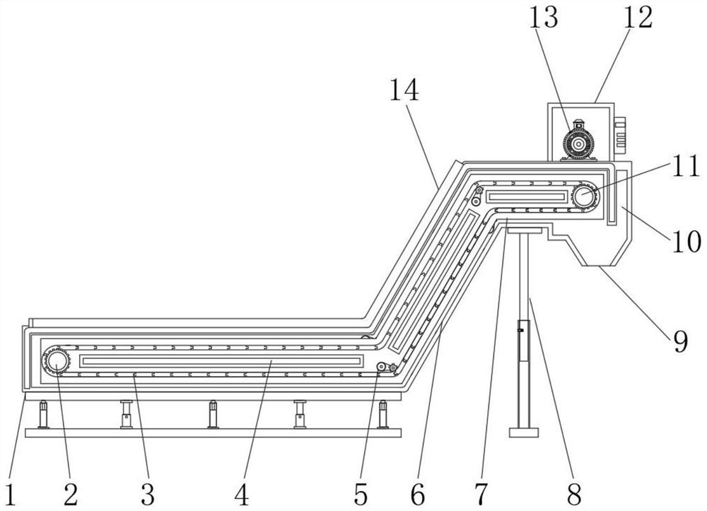
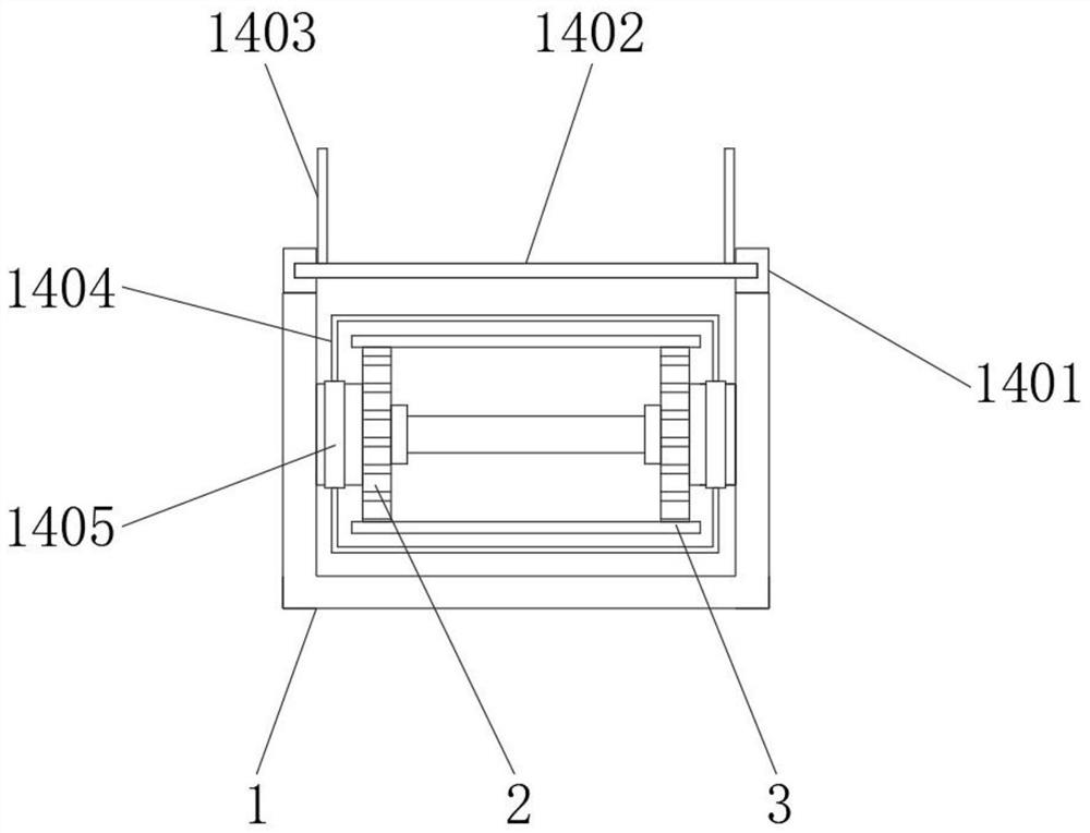
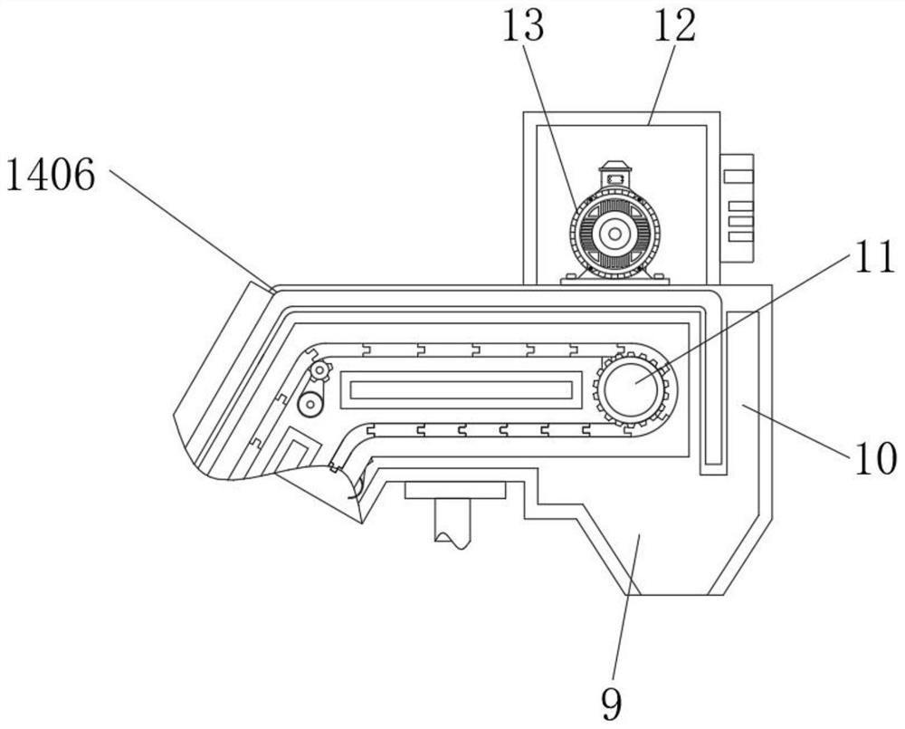
[0029] see Figure 1-8 , an embodiment provided by the present invention: a multi-function magnetic conveyor, including a conveying area 1, a bearing gear 2, a magnetic chain plate 3 and a magnetic strip 4, and the two sides inside the conveying area 1 are fixedly connected with bearing gears 2 , the outer side of the bearing gear 2 is meshed with a magnetic link plate 3, the interior of the magnetic link plate 3 is provided with a magnetic strip 4, the corner position of the magnetic link plate 3 is installed with an automatic tightening structure 5, and one side of the conveying area 1 is fixedly connected There is a climbing area 6, and one end of the climbing area 6 is fixedly connected with a falling off area 7, and one side of the bottom end of the falling off area 7 is fixedly connected with a lifting mechanism 8, and the other side of the bottom end of the falling off area 7 is provided with a leakage cover 9, A discharge port 10 is arranged on one side of the inside of the drop-off area 7, one end of the magnetic link plate 3 is engaged with a torque limiting structure 11, the top of the drop-off area 7 is fixedly connected with a power chamber 12, and the bottom end of the power chamber 12 is fixedly connected There is a servo motor 13, and a protective structure 14 is fixedly connected to the top of the conveying area 1;
[0030]An automatic tensioning structure 5 is installed at the corner of the magnetic link plate 3. The automatic tensioning structure 5 includes a transmission gear 501, a protective cover 502, a fixed bearing 503, a connecting block 504, a stopper 505, a rear cover 506, a connecting bearing 507, The front cover 508, the curved spring 509 and the fixing groove 510, the outer side wall of the transmission gear 501 is meshed and connected with the corner position of the magnetic link plate 3, the protection cover 502 is installed on both sides of the transmission gear 501, and the interior of the protection cover 502 penetrates There is a fixed bearing 503, and one side of the fixed bearing 503 is fixedly connected with a connecting block 504, and two sides of the bottom end of the connecting block 504 are fixedly connected with a block 505, and the bottom end of the block 505 is fixed with a back cover 506. A connecting bearing 507 runs through the inside, and a front cover 508 is installed on one side of the connecting bearing 507, a curved spring 509 is installed inside the front cover 508, a fixing groove 510 is arranged on the top of one side of the front cover 508, and the transmission gear 501 and the The interior of the fixed bearing 503 is in a rotating structure, the rear cover 506 and the front cover 508 are on the same horizontal plane, and a lifting mechanism 8 is fixedly connected to one side of the bottom end of the shedding area 7. The lifting mechanism 8 includes an inner tube 801, an outer tube 802, and a positioning groove. 803, the fixed spring 804, the limit block 805, the limit hole 806, the backing plate 807, the pneumatic telescopic rod 808, the telescopic connecting rod 809 and the bottom plate 810, the top end of the inner tube 801 is fixedly connected with the bottom end of the shedding area 7, and the inner tube The outside of 801 is wrapped with an outside tube 802, the inside of the inside tube 801 is provided with a positioning groove 803, and one side of the positioning groove 803 is fixed with a fixed spring 804, one side of the fixed spring 804 is fixed with a limit block 805, and the outside tube One side of 802 is provided with a limiting hole 806, the bottom end of the conveying area 1 is fixed with a backing plate 807, and one side of the bottom end of the backing plate 807 is fixed with a pneumatic telescopic rod 808, the model of the pneumatic telescopic rod 808 can be CQMB25, the pneumatic telescopic rod 808 The input end of the rod 808 is electrically connected with the output end of the control panel through a wire, one side of the pneumatic telescopic rod 808 is provided with a telescopic connecting rod 809, and the bottom end of the telescopic connecting rod 809 is fixed with a bottom plate 810;
[0031] Specifically, as figure 1 , Figure 4 , Figure 5 and Image 6 As shown in the figure, when using this mechanism, first, start using the conveyor after the height of the lifting mechanism 8 is adjusted. After the magnetic chain plate 3 operates for a long time, its internal parts are more likely to become loose, so that the overall distance between the magnetic chain plate 3 is Begin to elongate, when the magnetic link plate 3 is loose, its length must be longer than before. At this time, under the influence of the elastic force of the curved spring 509, the stopper 505 is offset by a certain angle by connecting the bearing 507, so that the fixed The connecting block 504 at the top of the stopper 505 is shifted together by a loose angle. At this time, the transmission gear 501 is simultaneously offset by the fixed bearing 503, and the angle at the position where the magnetic link plate 3 is engaged with the transmission gear 501 also changes accordingly. When the magnetic link plate 3 is loosened, the length of the magnetic link plate 3 is longer, and the angle of the offset of the stopper 505 is larger at this time, and the transmission gear 501 presses the corner position of the magnetic link plate 3 more and more, so that the magnetic link plate 3 is maintained as a whole. Compact state, so as to avoid the impact on the conveyor due to the loosening of the magnetic chain plate 3;
[0032] The torque limiting structure 11 includes a gear plate 1101 , a transmission rod 1102 , a fixed shaft sleeve 1103 , a flange plate 1104 , a meshing groove 1105 , a butterfly spring plate 1106 , a ball 1107 , a transmission bearing 1108 and an adjustment sleeve 1109 , the outer surface of the gear plate 1101 It is meshed with one end of the magnetic chain plate 3, a transmission rod 1102 is fixed on one side of the gear plate 1101, a fixed shaft sleeve 1103 is fixed on one side of the outer side wall of the transmission rod 1102, and a flange 1104 is fixed on one side of the fixed shaft sleeve 1103. , and one side of the flange 1104 is engaged with an engaging groove 1105, one side of the engaging groove 1105 is provided with a butterfly spring sheet 1106, the top of the engaging groove 1105 is engaged with a ball 1107, and the top of the ball 1107 is provided with a transmission bearing 1108 , and an adjusting sleeve 1109 is installed on one side of the transmission bearing 1108, the gear plate 1101 and the interior of the magnetic chain plate 3 are in a meshing structure, and the transmission bearing 1108 forms a rotating structure through the interior of the balls 1107;
[0033] Specifically, as figure 1 , Figure 7 and Figure 8 As shown in the figure, when using this mechanism, first of all, when there is too much debris on the aluminum alloy panel 1402 or the magnetic link plate 3 is stuck, so that the magnetic link plate 3 is forced to stop and cannot rotate normally, the servo motor 13 starts to automatically increase the power And the current increases, so that the torsion force of the transmission bearing 1108 increases. At this time, the butterfly spring piece 1106 senses that the current of the fixed bushing 1103 increases, and starts to attract the balls 1107, so that the balls 1107 are disengaged from the meshing grooves 1105, so that the transmission bearing 1108 During rotation, other parts cannot be driven to rotate by the engagement of the ball 1107 with the meshing groove 1105. At this time, since the ball 1107 is disengaged from the meshing groove 1105, the transmission bearing 1108 rotates alone, and the gear plate 1101 stops rotating. The power of the servo motor 13 is reduced accordingly, so that the conveyor has an overload protection function to avoid damage to the magnetic chain plate 3 and the servo motor 13 caused by overload operation;
[0034] The top of the conveying area 1 is fixedly connected with a protective structure 14. The protective structure 14 includes a blocking block 1401, an aluminum alloy panel 1402, a metal baffle 1403, a sealing box 1404, a connecting groove 1405 and an arc angle 1406. The bottom end of the blocking block 1401 is connected to the The top of the conveying area 1 is fixed, one side of the block 1401 is engaged with an aluminum alloy panel 1402, both sides of the top of the aluminum alloy panel 1402 are fixed with a metal baffle 1403, the outside of the magnetic chain plate 3 is wrapped with a sealing box 1404, and Both sides of the sealing box 1404 are provided with connecting grooves 1405, and the corner positions of the aluminum alloy panel 1402 are provided with arc corners 1406. The clamping block 1401 and the interior of the aluminum alloy panel 1402 are in a snap-fit structure, and the connecting grooves 1405 and the bearing Gear 2 is in the same horizontal plane;
[0035] Specifically, as figure 1 , figure 2 and image 3 As shown in the figure, when using this mechanism, firstly, the aluminum alloy panel 1402 is fixed on the inner side of the clamping block 1401 by the clamping block 1401 fixed at the top of the conveying area 1, and the metal alloy panel 1402 is fixed on both sides of the aluminum alloy panel 1402. The baffle 1403, when the debris falls on the surface of the aluminum alloy panel 1402, the metal debris starts to move slowly on the surface of the aluminum alloy panel 1402 due to the influence of the magnetic force of the magnetic link plate 3 and the magnetic strip 4. The outer side of the plate 3 is wrapped with a layer of sealing box 1404, and each component connected with the magnetic chain plate 3 enters its interior through the connecting grooves 1405 provided on both sides of the sealing box 1404, so that the interior of the sealing box 1404 maintains a sealed environment, so that the Metal chips cannot enter the interior of the magnetic chain plate 3, so that the magnetic transmission mechanism of the conveyor is sealed and protected to prevent metal chips from entering the interior of the transmission mechanism.
[0036] Working principle: When the present invention is in use, the multi-position magnetic conveyor is connected to an external power supply. First, the conveyor is towed to the bottom end of the CNC machine tool that produces metal scraps, and the position is adjusted to ensure that the metal scraps can fall vertically on the aluminum alloy. The surface of the panel 1402, then start the pneumatic telescopic rod 808 to lift the backing plate 807 and indirectly lift the conveyor, stop the pneumatic telescopic rod 808 when the height is suitable, and then press the limit block 805 to make the limit block 805 from the limit The inside of the hole 806 is separated, and then the inner tube 801 is pulled out, and the length is adjusted so that the limit block 805 is engaged from the appropriate limit hole 806 to support the shedding area 7, and then the magnetic conveyor is started, and the conveyor is normal. During operation, the balls 1107 are engaged in the meshing grooves 1105. At this time, the servo motor 13 rotates the transmission bearing 1108 through the transmission belt, thereby driving the flange 1104 to rotate normally through the balls 1107. With the normal rotation of the flange 1104, the inner The transmission rod 1102 of the aluminum alloy panel 1102 also rotates, thereby driving the gear plate 1101. At this time, the gear plate 1101 drives the magnetic chain plate 3 to rotate continuously. When the chain plate 3 is forced to stop and cannot rotate normally, the servo motor 13 starts to automatically increase the power and the current increases, so that the torsion force of the transmission bearing 1108 increases. The balls 1107 are adsorbed, so that the balls 1107 are disengaged from the engagement grooves 1105, so that the transmission bearing 1108 cannot drive other parts to rotate through the engagement of the balls 1107 and the engagement grooves 1105. , when the transmission bearing 1108 rotates alone, the gear plate 1101 stops rotating at this time, and the power of the servo motor 13 is reduced accordingly, so that the conveyor has an overload protection function to avoid overload operation. The magnetic chain plate 3 and the servo motor 13 cause damage;
[0037] Next, the clamping block 1401 fixed at the top of the conveying area 1 is engaged to fix the aluminum alloy panel 1402 on the inner side of the clamping block 1401, and the metal baffles 1403 are fixed on both sides of the aluminum alloy panel 1402. When falling on the surface of the aluminum alloy panel 1402, the metal debris starts to move slowly on the surface of the aluminum alloy panel 1402 due to the influence of the magnetic force of the magnetic link plate 3 and the magnetic strip 4. Due to the limitation of the metal baffle 1403, the metal debris It is impossible to enter the interior of the conveyor through the gap between the conveying area 1 and the aluminum alloy panel 1402. When the metal debris is too small, it may fall close to the interior of the conveyor. At this time, the outer side of the magnetic chain plate 3 is wrapped with a layer of The sealing box 1404, and each component connected with the magnetic chain plate 3 enters its interior through the connecting grooves 1405 provided on both sides of the sealing box 1404, so that the interior of the sealing box 1404 is kept in a sealed environment, so that metal debris cannot enter the magnetic chain Inside the plate 3, at the same time, the corners of the aluminum alloy panel 1402 are provided with curved corners 1406, so that the metal chips can pass through smoothly and reduce the probability of falling, so as to seal and protect the magnetic transmission mechanism of the conveyor. ;
[0038] Finally, after the magnetic chain plate 3 has been operated for a long time, its internal components are more likely to become loose, so that the overall distance of the magnetic chain plate 3 begins to lengthen. At this time, an automatic tightening structure 5 is installed at the corner of the magnetic chain plate 3 . , at this time, the transmission gear 501 is engaged with the chain in the magnetic chain plate 3, so that the angle of the magnetic chain plate 3 is shifted to a suitable angle, and the automatic tensioning structure 5 is fixed. It was lengthened before. At this time, due to the elastic force of the curved spring 509, the block 505 is displaced by a certain angle through the connecting bearing 507, so that the connecting block 504 fixed at the top of the block 505 is loosened and the angle is offset together. At the same time, the transmission gear 501 is offset by the fixed bearing 503, and the angle of the transmission gear 501 at the position of the magnetic link plate 3 also changes. When the magnetic link plate 3 is loosened, the length of the magnetic link plate 3 is longer. At this time, the larger the offset angle of the stopper 505 is, the more the transmission gear 501 presses the corner position of the magnetic link plate 3, so that the magnetic link plate 3 is kept in a compact state as a whole, and finally the magnetic conveying of the multi-position magnetic conveyor is completed. Work.
[0039] Although the present invention has been described in detail with reference to the foregoing embodiments, for those skilled in the art, it is still possible to modify the technical solutions described in the foregoing embodiments, or to perform equivalent replacements for some of the technical features. Any modification, equivalent replacement, improvement, etc. made within the spirit and principle of the present invention shall be included within the protection scope of the present invention.