

Installation clamp and installation method of ultrasonic flowmeter probe
A technology for ultrasonic flowmeters and installation fixtures, which is applied in the direction of measuring devices, volume measurement, and measurement flow/mass flow, etc., which can solve the problem of inability to accurately locate the installation position of ultrasonic flowmeters, increase the uncertainty of human judgment, and make it difficult to achieve high-precision detection and other issues, to achieve the effect of good compatibility, high precision, and precise installation
- Summary
- Abstract
- Description
- Claims
- Application Information
AI Technical Summary
Problems solved by technology
Method used
Image

Examples
Embodiment 1
[0043] The invention provides a technical solution:
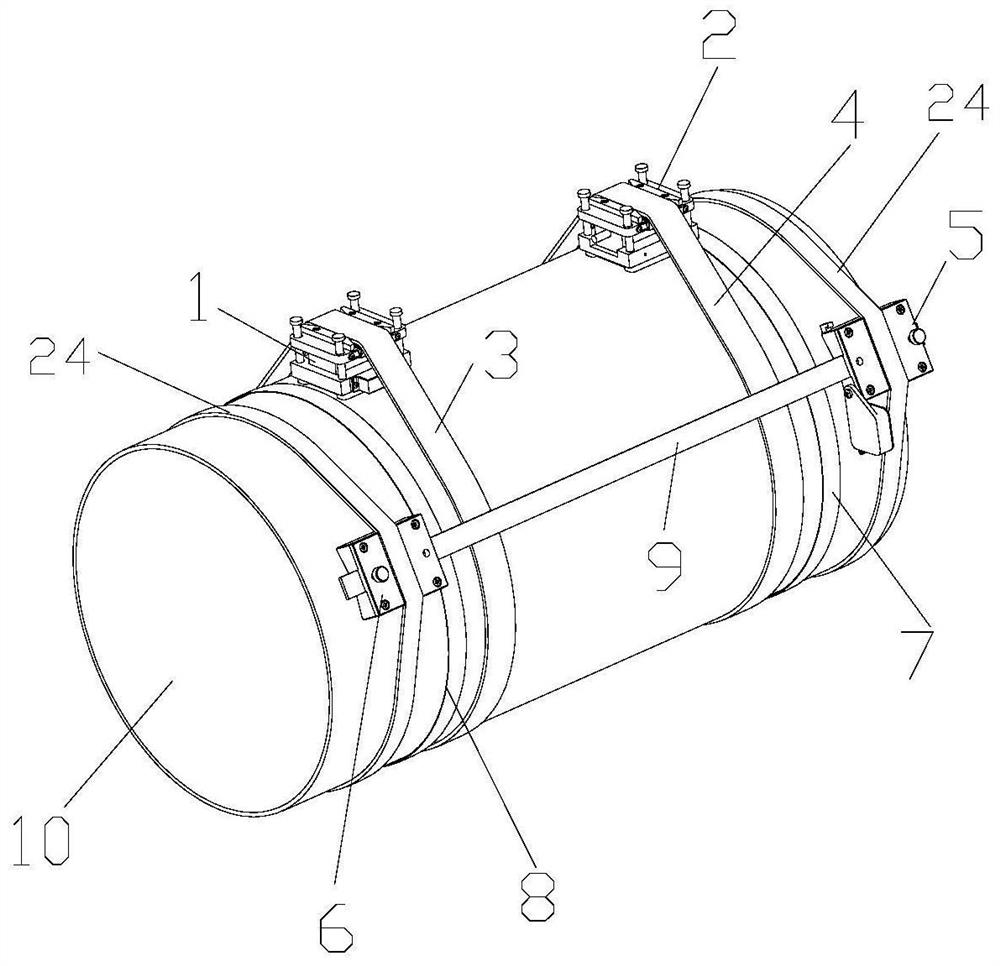
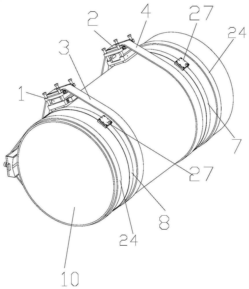
[0044] Please refer to Figure 1-2 , a mounting fixture for an ultrasonic flowmeter probe, comprising a first fixture seat 1, a second fixture seat 2, a first fastening belt 3, a second fastening belt 4, a first right-angle seat 5, a second right-angle seat 6, The first ruler 7, the second ruler 8 and the steel ruler 9, the first right-angle seat 5 is fixedly installed on the first end face of the pipeline 10, and the second right-angle seat 6 is installed on the second end surface of the pipeline 10, so The first end of the steel ruler 9 is connected to the first right-angle seat 5, the second end of the steel ruler 9 is connected to the second right-angle seat 6, and the steel ruler 9 is connected to the center of the pipeline 10. The axes are parallel, the first ruler 7 is wound on the outer wall of the pipeline 10 through the first right-angle seat 5 , and the second ruler 8 is wound on the pipe 10 through the second r...
Embodiment 2
[0062] A method for installing an ultrasonic flowmeter probe, using the installation fixture of the ultrasonic flowmeter probe for installation, comprising the following steps:
[0063] S1, the first right-angle seat 5 is installed: the first right-angle seat 5 is placed on the outer wall of the second end face of the pipeline 10, and the first right-angle seat 5 is fixed on the second end face of the pipeline 10 by the positioning seat 26;
[0064] Specifically, the first right-angle seat 5 is first placed near the second end face of the pipeline 10, and a positioning seat 26 is rotated on the first right-angle seat 5, and the rotation positioning seat 26 fixes the first right-angle seat 5 on the outer wall of the pipeline 10, Make the first right-angle seat 5 a fixed measurement reference point.
[0065] S2. Install the first ruler 7: insert one end of the first ruler 7 into the vertical positioning groove 20 of the first right-angle seat 5, closely fit the outer wall of the...
PUM
 Abstract
Description
Claims
Application Information