Force measuring device for accurately measuring friction coefficient and support calibration method

A force measuring device and friction coefficient technology, applied in the direction of measuring device, mechanical device, force/torque/work measuring instrument, etc., can solve the problems of low accuracy of friction coefficient measurement, inaccurate vertical force, etc. Safety, ensure accurate monitoring, accurate vertical force calibration effect

Pending Publication Date: 2021-05-04
DATONG INC
View PDF0 Cites 4 Cited by
  • Summary
  • Abstract
  • Description
  • Claims
  • Application Information

AI Technical Summary

Problems solved by technology

[0004] The object of the present invention is to provide a force measuring device and a support calibration method for accurately measuring the friction coefficient, so as to solve th...

Method used


Image

  • Force measuring device for accurately measuring friction coefficient and support calibration method
  • Force measuring device for accurately measuring friction coefficient and support calibration method
  • Force measuring device for accurately measuring friction coefficient and support calibration method

Examples


Embodiment 1

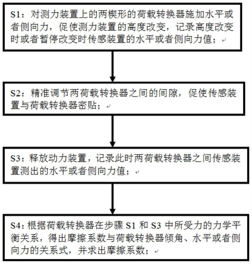
[0041] Such as figure 1 , 2, Shown in 3, a kind of force-measuring device and support calibration method based on accurate determination of friction coefficient, comprises the following steps:

[0042] S1: Apply a horizontal or lateral force to the two wedge-shaped load converters 3 on the force measuring device, so that the two load converters 3 are far away from each other, thereby promoting the height of the force measuring device to rise, and the sensor is recorded when the height changes or when the change is paused Horizontal or lateral force value T of device 5 1 ;

[0043] S2: Precisely adjust the gap between the two load converters 3, so that the sensing device 5 and the load converter 3 are closely attached;

[0044] S3: release the power device 13, and record the horizontal or lateral force value T measured by the sensing device 5 between the two load converters 3 at this time 2 ;

[0045] S4: According to the mechanical balance relationship of the load convert...

Embodiment 2

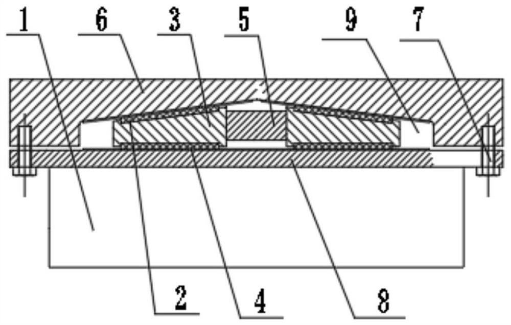
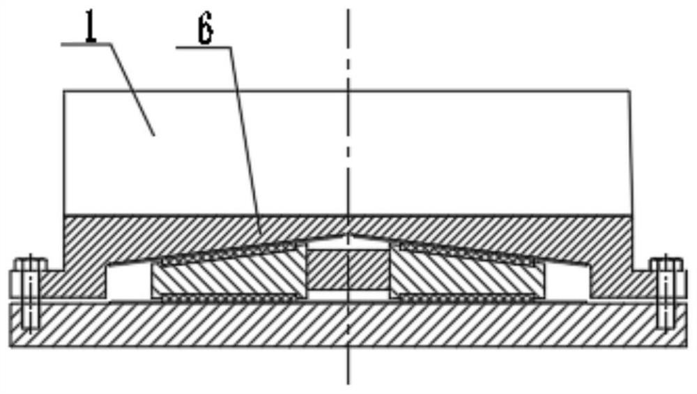
[0049] In this embodiment, in step S1, the force measuring device used in the method includes an upper adjustment plate 6 and a lower adjustment plate 8, such as figure 1 with 4 As shown, a support core 1 is provided above the upper adjustment plate 6 or below the lower adjustment plate 8. The support core 1 can be a spherical support, a friction pendulum support, a rubber support, a shock-absorbing and isolation support, etc., and the upper The bottom surface of the adjustment plate 6 is provided with an adjustment cavity 9, and two load converters 3 are arranged in the adjustment cavity 9, and the upper adjustment plate 6 and the lower adjustment plate 8 are fixed by bolts 7 and the two load converters 3 are limited in the adjustment cavity 9 , the top surface of the load converter 3 is in direct contact with the top surface of the adjustment chamber 9, the adjustment chamber 9 is in an inverted V shape, the bottom surface of the load converter 3 is in plane contact with the...

Embodiment 3

[0057] Such as Figure 8-11 As shown, in this embodiment, the limiting device adopts two wedge-shaped blocks 14, the inclined surfaces of the two wedge-shaped blocks 14 are matched with each other, and the mutual sliding of the two wedge-shaped blocks 14 is adjusted to the sensing device 5 and the load converter 3 Closely attached, the rest are the same as in Embodiment 2. The two wedge blocks 14 can precisely adjust the gap between the sensing device 5 and the load converter 3 by sliding up and down or sliding forward and backward, so that the sensing device 5 and the load The converter 3 is closely attached, and utilizes the leverage principle of the wedge block 12, so that a relatively large lateral force (the force is in the horizontal direction) can be obtained with a small force (the force is in the same direction as the mutual sliding direction of the two wedge blocks 12), Thereby reach the purpose that sensing device 5 and load converter 3 stick closely together, make ...


PUM


Abstract

The invention discloses a force measuring device based on accurate friction coefficient measurement and a support calibration method, and the method comprises the following steps of: applying a horizontal or lateral force to two wedge-shaped load converters on the force measuring device, promoting the height of the force measuring device to change, and recording a horizontal or lateral force value of a sensing device when the height is changed or the change is paused; precisely adjusting the gap between the two load converters to promote tight attachment of the sensing device and the load converters; releasing a power device, and recording a horizontal or lateral force value measured by the sensing device between the two load converters at the moment; according to the mechanical equilibrium relationship of the stress of the load converters, acquiring a relational expression between the friction coefficient and the inclination angle and the horizontal or lateral force of the load converters, and solving the friction coefficient; the friction coefficient can be accurately calculated in a service state of the force measuring device, and the vertical force can be accurately calibrated.

Description

technical field [0001] The invention relates to the technical field of rail transit structural engineering, and can also be applied to structural engineering fields such as highways, municipal administration, and construction, and specifically relates to a force measuring device and a support calibration method for accurately measuring friction coefficients. Background technique [0002] The force-measuring device and the support are used to measure the force of the force-transmitting components between structures, and are widely used in various fields, especially in the field of bridge engineering. The change of the force of the device can reflect the overall operation of the bridge to a large extent, and realize the collection of monitoring data of the bridge support, that is, the vertical reaction force of the bridge, which can provide a technical basis for the health monitoring of the bridge. With the increase of highway and railway bridge construction in our country yea...

Claims


Application Information

Patent Timeline
IPC IPC(8): G01N19/02G01L5/168
CPCG01L5/168G01N19/02
Inventor 伍大成王剑明邹贻军胡盟
Owner DATONG INC
Why Eureka
Try Eureka