

Arm strength training equipment for sports
A technology for training equipment and arm strength, which is applied in the field of training equipment and can solve problems such as smashing others, hand injuries, and low safety
- Summary
- Abstract
- Description
- Claims
- Application Information
AI Technical Summary
Problems solved by technology
Method used
Image

Examples
Embodiment 1
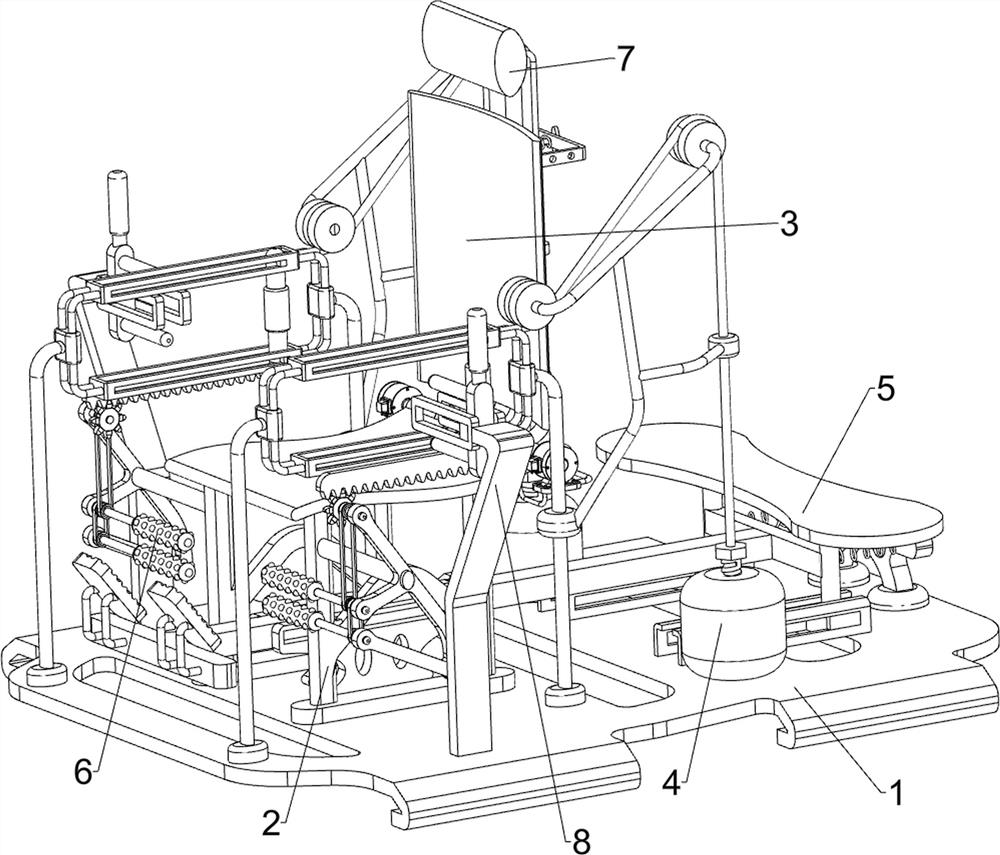
[0028] A kind of arm strength training equipment for sports, such as Figure 1-4 As shown, it includes a chassis 1, a support seat 2, a backrest assembly 3 and a tension mechanism 4. The left side of the top of the chassis 1 is connected with a support seat 2, and the top of the support seat 2 is connected with a backrest assembly 3. Both front and rear sides are connected with tension mechanism 4.
[0029] The back assembly 3 includes a low-speed motor 31, a rotating shaft 32 and a backing plate 33. The front and rear ends on the right side of the support base 2 are connected with a low-speed motor 31, and the output shafts of the low-speed motors 31 on both sides are connected with a rotating shaft 32. On the rotating shaft 32 A backing plate 33 is connected.
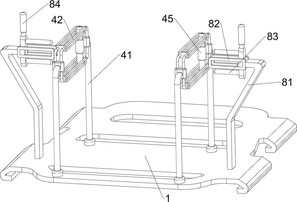
[0030] The tension mechanism 4 includes a first fixed frame 41, a first guide carriage 42, a first guide frame 43, a guide wheel 44, a first handle 45, a rope 46, a threaded bolt 47 and an iron block 48, and the left...
Embodiment 2
[0033] On the basis of Example 1, such as Figure 4-6 As shown, a supporting mechanism 5 is also included, and the supporting mechanism 5 includes a second sliding guide frame 51, a first supporting frame 52, a baffle frame 53, a first spring 54, a third guiding sliding frame 55, a connecting frame 56 and a pedal 57, the front and rear sides of the right side of the underframe 1 are connected with a second guide carriage 51, the first support frame 52 is slidably connected between the second guide carriages 51 on both sides, and the right end of the underframe 1 is connected with a The baffle frame 53, three first springs 54 are connected between the baffle frame 53 and the first support frame 52, the left middle part of the underframe 1 is connected with a third guide carriage 55, and the third guide carriage 55 is of sliding type A connecting frame 56 is connected to the ground, the right end of the connecting frame 56 is connected with the first supporting frame 52 , and th...
Embodiment 3
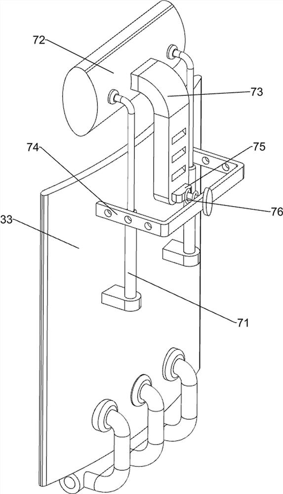
[0038] On the basis of Example 2, such as Figure 7-8 Shown, also comprise elevating mechanism 7, elevating mechanism 7 comprises telescoping bar 71, headrest 72, positioning frame 73, the second guide frame 74, wedge-shaped block 75 and the second spring 76, the right side of back plate 33 is connected with Two telescopic rods 71, two telescopic rods 71 are arranged symmetrically front and rear, a headrest 72 is connected between the two telescopic rods 71, and a positioning frame 73 is connected to the right side of the headrest 72, and the positioning frame 73 is evenly spaced to have draw-in slots , the upper right side of the leaning plate 33 is connected with a second guide frame 74, the second guide frame 74 is slidably connected with a wedge-shaped block 75, the wedge-shaped block 75 cooperates with the draw-in groove, and the wedge-shaped block 75 and the second guide slide A second spring 76 is connected between the frames 51 .
[0039] People can adjust the heigh...
PUM
 Abstract
Description
Claims
Application Information