Arc steel bar bending and cutting all-in-one machine for cement well lid pouring
A steel bar bending and integrated machine technology, which is applied in the field of an arc steel bar bending and cutting integrated machine for cement manhole cover casting, and can solve the problems of inability to cut steel bars, labor-intensive and other problems.
- Summary
- Abstract
- Description
- Claims
- Application Information
AI Technical Summary
Problems solved by technology
Method used
Image
Examples
Embodiment 1
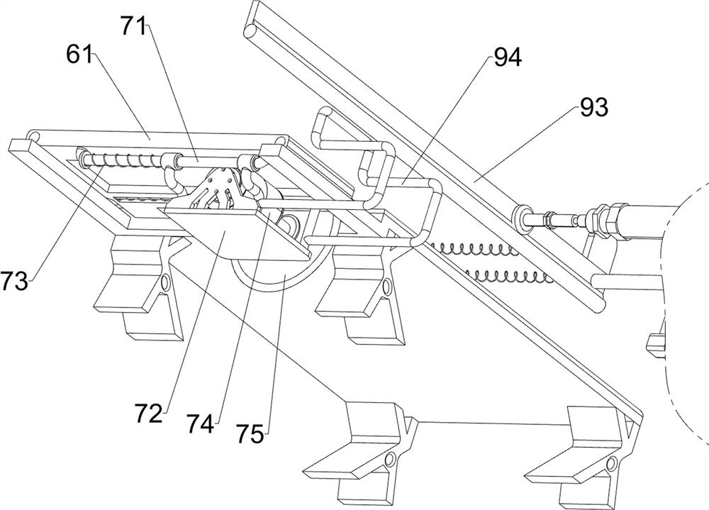
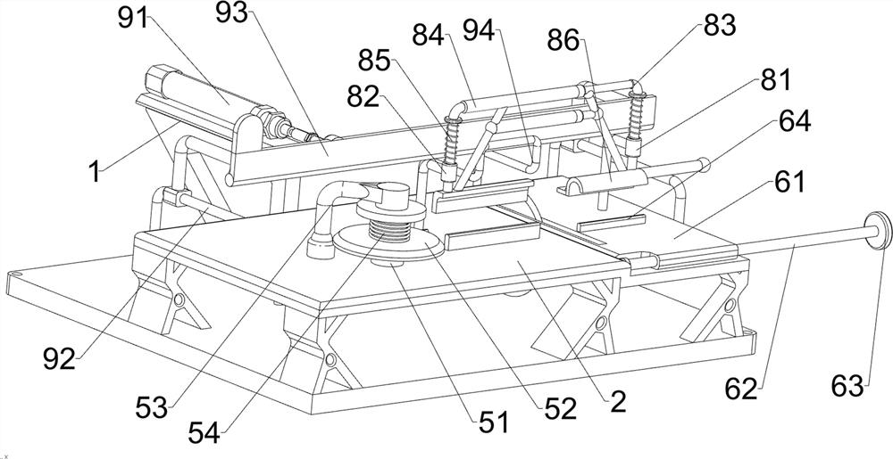
[0027] An integrated machine for bending and cutting arc steel bars for cement manhole cover pouring, such as Figure 1 to Figure 3 As shown, it includes a base 1, a mounting plate 2, a first limiting plate 3 and a second limiting plate 4, the top of the base 1 is connected with the mounting plate 2, and the top of the mounting plate 2 is connected with the first limiting plate 3 and the second limiting plate 4. The second limiting plate 4, the first limiting plate 3 and the second limiting plate 4 are arranged in a staggered manner, and also include a bending component 5, an adjusting component 6, a cutting component 7, a pressing component 8 and a pushing component 9, and the installation The plate 2 is provided with a bending assembly 5 and an adjustment assembly 6, the adjustment assembly 6 is provided with a cutting assembly 7, a pressing assembly 8 is provided between the adjustment assembly 6 and the mounting plate 2, and a cutting assembly 7 and the base 1 are provided....
Embodiment 2
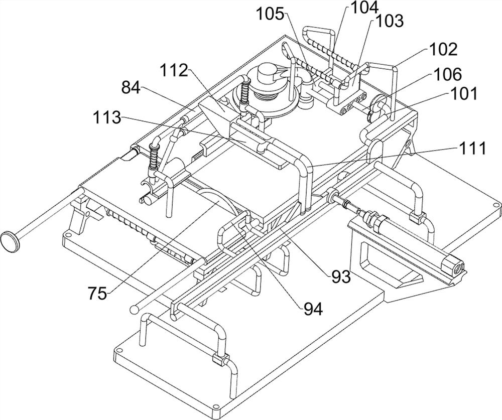
[0035] On the basis of Example 1, such as Figure 4 As shown, the extrusion assembly 10 is also included, the extrusion assembly 10 includes a push frame 101, a third guide rail 102, a sliding sleeve 103, a second compression spring 104, a second push plate 105 and a second screw rod 106, the first push A push frame 101 is connected to the plate 93, a third guide rail 102 is connected to the left side of the top of the mounting plate 2, and a sliding sleeve 103 is slidably connected to the third guide rail 102, and a second compression frame is connected between the sliding sleeve 103 and the third guide rail 102. The spring 104 and the sliding sleeve 103 are slidably connected with a second push plate 105 , and the second push plate 105 is rotatably connected with a second screw rod 106 , and the second screw rod 106 is screwed with the sliding sleeve 103 .
[0036] When the first push plate 93 moves forward, it drives the pushing frame 101 to move forward together. When the ...
Embodiment 3
[0038] On the basis of Example 2, such as Figure 4 As shown, the pressing assembly 11 is also included. The pressing assembly 11 includes a second connecting frame 111, a wedge block 112 and a fixing plate 113. The top of the first push plate 93 is connected with a second connecting frame 111. The second connecting frame 111 A wedge block 112 is connected to it, and the wedge block 112 cooperates with the third sliding frame 84 .
[0039] The first push plate 93 drives the second connection frame 111 to move forward when moving forward, and the second connection frame 111 drives all devices on it to move forward together when the second connection frame 111 moves forward. After the sliding frame 84 is in contact, the wedge block 112 continues to move forward to push the third sliding frame 84 to move downward. In this way, there is no need to manually press the third sliding frame 84 to move downward, which effectively saves manpower.
PUM
 Abstract
Description
Claims
Application Information
 - R&D Engineer
- R&D Manager
- IP Professional
- Industry Leading Data Capabilities
- Powerful AI technology
- Patent DNA Extraction
Browse by: Latest US Patents, China's latest patents, Technical Efficacy Thesaurus, Application Domain, Technology Topic, Popular Technical Reports.
© 2024 PatSnap. All rights reserved.Legal|Privacy policy|Modern Slavery Act Transparency Statement|Sitemap|About US| Contact US: help@patsnap.com


