High-pressure stacking frame for interlayer door and window glass
A door and window glass, high-pressure technology, applied in the direction of external frames, containers, packaging items types, etc.
- Summary
- Abstract
- Description
- Claims
- Application Information
AI Technical Summary
Problems solved by technology
Method used
Image

Examples
Embodiment Construction
[0038] Specific embodiments of the present invention will be described in detail below in conjunction with the accompanying drawings. It should be understood that the specific embodiments described here are only used to illustrate and explain the present invention, and are not intended to limit the present invention.
[0039] In the present invention, unless otherwise specified, the orientation words included in the term such as "up, down, left, right, front, back, inside and outside" only represent the orientation of the term in the normal use state, or the common name understood by those skilled in the art. , and should not be construed as a limitation of this term.
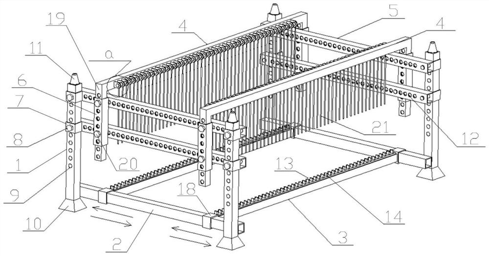
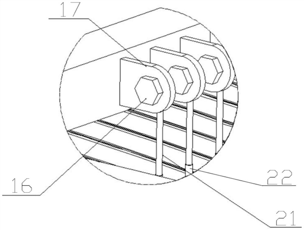
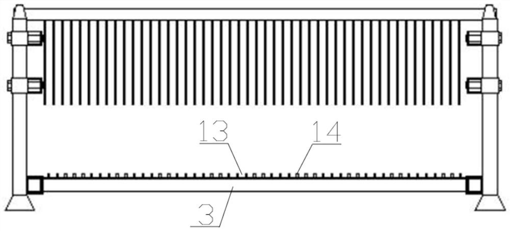
[0040] see Figure 1-10 The high-pressure stacking frame for laminated door and window glass shown, the high-pressure stacking frame for laminated door and window glass includes: four columns 1 distributed in a matrix, and connecting rods 2 are fixedly connected between the bottoms of the two columns 1 on the ...
PUM
 Abstract
Description
Claims
Application Information
PatSnap Eureka turns technology decisions into work you can execute. Powered by our Innovation Knowledge Graph, it runs expert workflows across engineering, life sciences, materials and intellectual property. Get your review-ready output in minutes.


