Acting conversion type fitness equipment
A kind of fitness equipment and work-making technology, applied in mechanical equipment, sports accessories, electromechanical devices, etc., can solve the problems of reuse, time-consuming, and inability to transform
- Summary
- Abstract
- Description
- Claims
- Application Information
AI Technical Summary
Problems solved by technology
Method used
Image


Examples
specific Embodiment approach 1
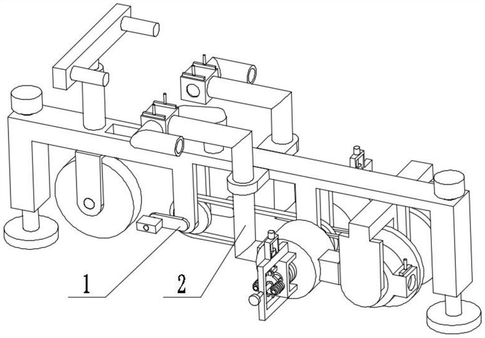
[0028] Combine below figure 1 , figure 2 , image 3 , Figure 4 , Figure 5 , Figure 6 , Figure 7 , Figure 8 , Figure 9 , Figure 10 , Figure 11 , Figure 12 , Figure 13 , Figure 14 Describe this embodiment, the present invention relates to a kind of fitness equipment, more specifically, a kind of exercise conversion type fitness equipment, including a pedal transmission mechanism 1, a frame mechanism 2, the equipment can provide exercise, and the equipment can convert the kinetic energy of the exercise into Converted into electrical energy, the device can switch the use state, and the device can switch the use of wind power according to the use.
[0029] The pedal transmission mechanism 1 is connected with the vehicle frame mechanism 2 .
specific Embodiment approach 2
[0031] Combine below figure 1 , figure 2 , image 3 , Figure 4 , Figure 5 , Figure 6 , Figure 7 , Figure 8 , Figure 9 , Figure 10 , Figure 11 , Figure 12 , Figure 13 , Figure 14Describe this embodiment, this embodiment will further explain Embodiment 1, described pedal transmission mechanism 1 comprises pedal 1-1, belt shaft turning arm 1-2, rotating shaft 1-3, sprocket wheel 1-4, Chain 1-5, wind wheel 1-6, friction disc 1-7, connecting shaft 1-8, pulley 1-9, belt 1-10, coil 1-11, rear wheel 1-12, belt shaft pulley 1-13 , sprocket wheel I1-14, pedal 1-1 is connected with belt shaft rotating arm 1-2 rotation, and belt shaft rotating arm 1-2 links to each other with rotating shaft 1-3, and rotating shaft 1-3 links to each other with sprocket wheel 1-4, The sprocket 1-4 is connected with the chain 1-5, the chain 1-5 is connected with the sprocket I1-14, the sprocket I1-14 is connected with the connecting shaft 1-8, and the connecting shaft 1-8 is connecte...
specific Embodiment approach 3
[0033] Combine below figure 1 , figure 2 , image 3 , Figure 4 , Figure 5 , Figure 6 , Figure 7 , Figure 8 , Figure 9 , Figure 10 , Figure 11 , Figure 12 , Figure 13 , Figure 14 Describe this embodiment, this embodiment will further explain Embodiment 1, described vehicle frame mechanism 2 comprises vehicle frame 2-1, front wheel 2-2, front wheel frame 2-3, support plate 2-4, belt screw Moving head threaded column 2-5, rotating shaft I2-6, handlebar 2-7, air outlet 2-8, conversion bellows 2-9, switch plate with handle 2-10, switch plate I2-11 with handle, switch air outlet Pipe 2-12, connecting pipe 2-13, connecting pipe support 2-14, bearing seat 2-15, air inlet 2-16, filter plate with handle 2-17, negative pressure box 2-18, magnetic field providing seat 2- 19. Wind wheel box 2-20, door type support 2-21, friction disc I2-22, bearing seat I2-23, bell plate 2-24, nut 2-25, threaded column 2-26, rotating seat 2-27 , card slot 2-28, threaded column wit...
PUM
 Abstract
Description
Claims
Application Information
 - R&D
- Intellectual Property
- Life Sciences
- Materials
- Tech Scout
- Unparalleled Data Quality
- Higher Quality Content
- 60% Fewer Hallucinations
Browse by: Latest US Patents, China's latest patents, Technical Efficacy Thesaurus, Application Domain, Technology Topic, Popular Technical Reports.
© 2025 PatSnap. All rights reserved.Legal|Privacy policy|Modern Slavery Act Transparency Statement|Sitemap|About US| Contact US: help@patsnap.com