
Image optical flow optimization method and system based on residual field and displacement field

A displacement field and flow optimization technology, applied in image analysis, image enhancement, image data processing, etc., can solve the problems of image sequence edge blur, limited application, excessive smoothing, etc., to achieve good calculation accuracy and improve the accuracy of optical flow field Effect

Active Publication Date: 2021-05-07
NANCHANG HANGKONG UNIVERSITY
View PDF5 Cites 1 Cited by
  • Summary
  • Abstract
  • Description
  • Claims
  • Application Information

AI Technical Summary

Problems solved by technology

[0003] At present, the optical flow estimation technology based on the convolutional neural network is the most commonly used optical flow estimation technology in the image sequence optical flow calculation technology. The blurring of image sequences with rigid motion and large displacement is more serious, which limits the application of such methods in various fields

Method used


Image

  • Image optical flow optimization method and system based on residual field and displacement field
  • Image optical flow optimization method and system based on residual field and displacement field
  • Image optical flow optimization method and system based on residual field and displacement field

Examples


Embodiment Construction

[0047] The following will clearly and completely describe the technical solutions in the embodiments of the present invention with reference to the accompanying drawings in the embodiments of the present invention. Obviously, the described embodiments are only some, not all, embodiments of the present invention. Based on the embodiments of the present invention, all other embodiments obtained by persons of ordinary skill in the art without making creative efforts belong to the protection scope of the present invention.

[0048] In order to make the above objects, features and advantages of the present invention more comprehensible, the present invention will be further described in detail below in conjunction with the accompanying drawings and specific embodiments.

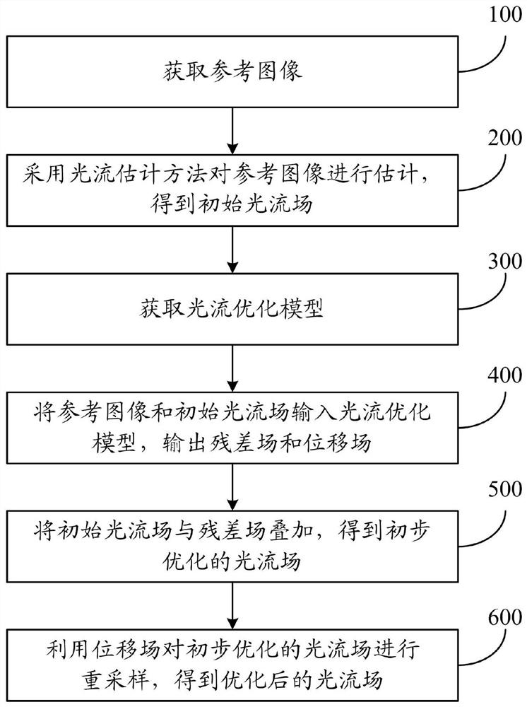
[0049] figure 1 It is a schematic flowchart of the image optical flow optimization method based on the residual field and the displacement field of the present invention. Such as figure 1 As shown, the image opt...


PUM


Abstract

The invention relates to an image optical flow optimization method and system based on a residual field and a displacement field. The method comprises the following steps: acquiring a reference image; estimating the reference image by adopting an optical flow estimation method to obtain an initial optical flow field; obtaining an optical flow optimization model, wherein the optical flow optimization model comprises an image encoder, an optical flow encoder, a first decoder and a sub-decoder; inputting the reference image and the initial optical flow field into the optical flow optimization model, and outputting a residual field and a displacement field; superposing the initial optical flow field and the residual field to obtain a preliminarily optimized optical flow field; and resampling the preliminarily optimized optical flow field by using the displacement field to obtain an optimized optical flow field. According to the invention, the precision and robustness of the image sequence optical flow estimation in the motion boundary region can be improved.

Description

technical field [0001] The invention relates to the field of image sequence optical flow calculation, in particular to an image optical flow optimization method and system based on a residual field and a displacement field. Background technique [0002] Optical flow is the two-dimensional instantaneous velocity of moving objects or pixel points on the surface of the scene on the projection plane. It can not only provide motion parameter information of moving objects and scenes in the image, but also provide rich three-dimensional structure information. It is an important tool in image processing, computer vision, etc. hot issues in the field. In recent years, with the rapid development of deep learning theory and technology, the convolutional neural network model has been widely used in the research of optical flow estimation technology. Because this type of method has significant advantages such as fast calculation speed and high stability, it has gradually become an import...

Claims


Application Information

Patent Timeline
Patent Type & Authority Applications(China)
IPC IPC(8): G06T7/246G06T7/269
CPCG06T7/246G06T7/269G06T2207/10016G06T2207/20081G06T2207/20084G06T2207/20016Y02T10/40G06T7/248
Inventor 张聪炫冯诚陈震胡卫明黎明陈昊
Owner NANCHANG HANGKONG UNIVERSITY
Learn More