A dry-type transformer using solar energy

A dry-type transformer, solar energy technology, applied in the direction of transformer/reactor installation/support/suspension, etc., can solve the problems of reduced base swing collision force, line failure, affecting line use, etc., to improve the utilization rate of light energy, The effect of reducing the swing collision force and prolonging the service life

Active Publication Date: 2021-10-01
ZHONGBIAN GRP SHANGHAI TRANSFORMER CO LTD
View PDF0 Cites 0 Cited by
  • Summary
  • Abstract
  • Description
  • Claims
  • Application Information

AI Technical Summary

Problems solved by technology

[0004] Aiming at the deficiencies of the prior art, the present invention provides a dry-type transformer using solar energy, which has the advantages of buffering the swaying force of the dry-type transformer when the wind force is strong, thereby reducing the swinging collision force of the base, etc. , to solve the problem that when the dry-type transformer is installed or the outside wind is strong, the impact will easily cause the dry-type transformer to vibrate, and the vibration of the dry-type transformer will cause the fixed part of the dry-type transformer to loosen, which will cause the internal structure of the dry-type transformer to appear. Damage, and the continuous vibration of the dry-type transformer will make the dry-type transformer prone to working failure, causing line failure and affecting the use of the line

Method used


Image

  • A dry-type transformer using solar energy
  • A dry-type transformer using solar energy
  • A dry-type transformer using solar energy

Examples


Embodiment 1

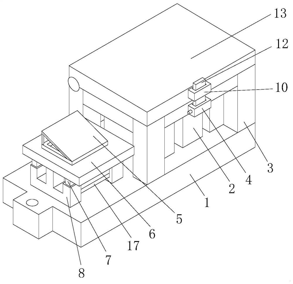
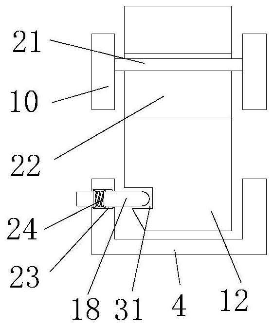
[0031] see Figure 1-Figure 2, the present invention provides a technical solution: a dry-type transformer utilizing solar energy, including a base 1, the top of the base 1 is fixedly connected with a first support frame 3, and the top of the first support frame 3 is rotatably connected with a cover plate 13, the cover The plate 13 can be rotated on the top of the first support frame 3, and the top of the base 1 is fixedly linked with a dry-type transformer 2, which is an existing structure and will not be described here. The dry-type transformer 2 is located on the first support The inside of the frame 3 is in contact with it. The front side of the first support frame 3 is fixedly connected with the first fixed block 4. The inside of the first fixed block 4 is a hollow structure, and the front side of the cover plate 13 is fixedly connected with the second fixed block. block 10, the inside of the second fixed block 10 is a hollow structure, the inside of the second fixed bloc...

Embodiment 2

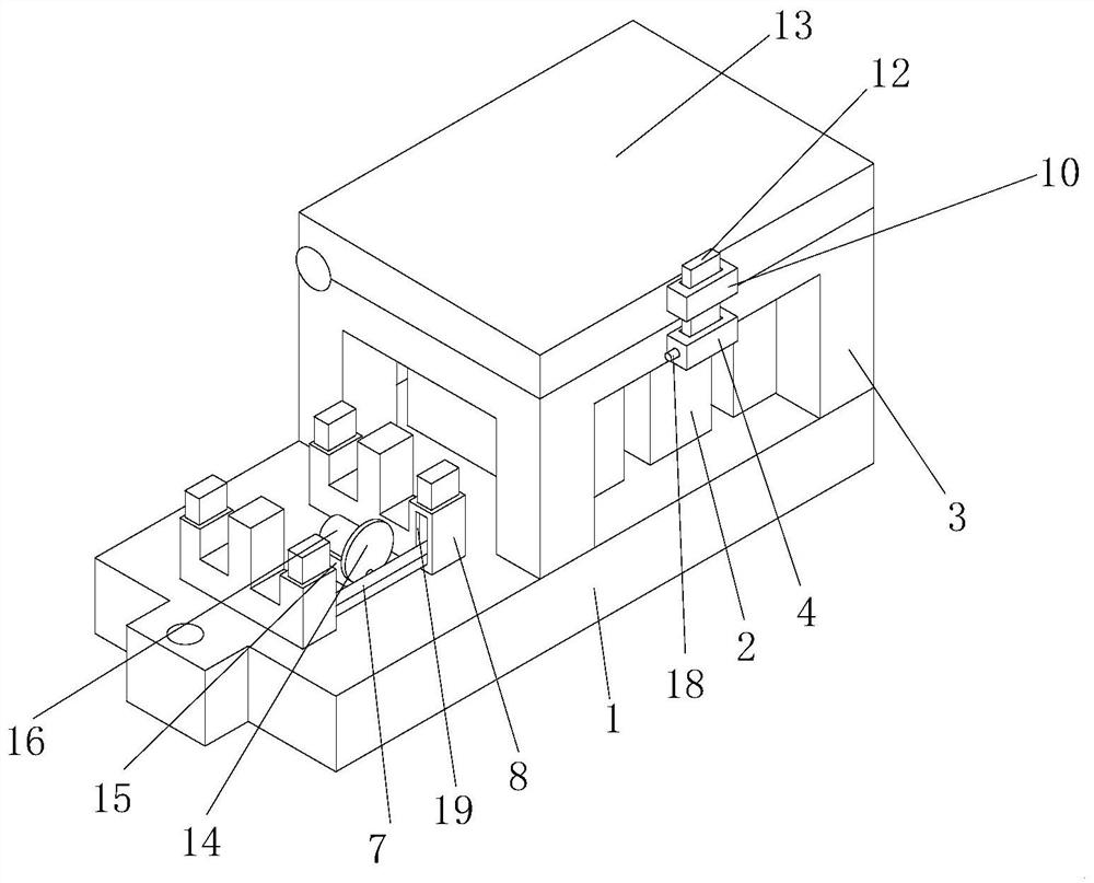
[0034] see Figure 3-Figure 5 , on the basis of Embodiment 1, the top of the base 1 is fixedly connected with a third fixed block 15, and the top of the third fixed block 15 is fixedly connected with a motor 16, and the motor 16 is an existing structure, which will not be repeated here. The motor 16 is connected to an external power source to start. The output end of the motor 16 is fixedly connected with a rotating plate 14, and the front side of the rotating plate 14 is fixedly connected with a rotating rod 20. When the plate 14 rotates, the rotating rod 20 can follow the rotating plate 14 to rotate eccentrically. The vertical left side of the front and rear sides of the second support frame 8 is provided with a first sliding groove 19, and the vertical rods on the front and rear sides of the second support frame 8 The inside of the second support frame 8 is a hollow structure, and the inside of the vertical rods on both sides of the second support frame 8 is provided with t...

Embodiment 3

[0037] see Figure 6 , on the basis of Embodiment 1, the inside of the cover plate 13 is provided with a first moving groove 9, the number of the first moving groove 9 is two, and the inside of the two first moving grooves 9 is provided with the same structure, the first The vertical section of the moving groove 9 is cross-shaped, and the inside of the first moving groove 9 is slidably connected with a first slide block 11, and the first slide block 11 can move in the inside of the first moving groove 9, and the first slide block 11 The top is rotatably connected with a transmission plate 17, the transmission plate 17 can be rotated on the top of the first slider 11, the bottom of the transmission plate 17 is rotatably connected with a second slider 28, and the transmission plate 17 can be rotated on the top of the second slider 28. Rotate, the bottom of the second slider 28 is provided with a relief plate 26, the top of the relief plate 26 is provided with a first chute 27, t...


PUM


Abstract

The invention relates to the technical field of dry-type transformers, and discloses a dry-type transformer utilizing solar energy, comprising a base, the top of the base is fixedly connected with a first support frame, the top of the first support frame is rotatably connected with a cover plate, and the base A dry-type transformer is fixedly connected to the top of the first support frame, and the dry-type transformer is located inside the first support frame and contacts with it. The front side of the first support frame is fixedly connected with a first fixed block, and the inside of the first fixed block is a hollow structure. The dry-type transformer using solar energy, after fixing the position of the cover plate and the first support frame, reduces the swinging collision force of the base, protects the dry-type transformer, and effectively prolongs the service life of the dry-type transformer. At the same time, the stability of the base is ensured, and to a certain extent, the internal structure of the dry-type transformer is prevented from being damaged, which in turn affects the use of the dry-type transformer, thereby enabling better use of the dry-type transformer.

Description

technical field [0001] The invention relates to the technical field of dry-type transformers, in particular to a dry-type transformer utilizing solar energy. Background technique [0002] Transformers are widely used in daily life. A transformer is a static electrical appliance that uses the principle of electromagnetic induction to convert one level of voltage and current into another level of voltage at the same frequency between two or more coils. and current, and transmit electric energy, transformers are divided into oil-immersed transformers, fully sealed transformers, combined transformers and dry-type transformers, among which dry-type transformers are widely used in local lighting, high-rise buildings, airports, wharf CNC machinery and other places, simple The dry-type transformer refers to the transformer whose iron core and winding are not immersed in insulating oil; some current dry-type transformers are directly fixed by bolts; but when the dry-type transformer ...

Claims


Application Information

Patent Timeline
Patent Type & Authority Patents(China)
IPC IPC(8): H01F27/06
CPCH01F27/06
Inventor 黄信乐陶进黄伟
Owner ZHONGBIAN GRP SHANGHAI TRANSFORMER CO LTD
Why Eureka
Try Eureka