
Intelligent vacuum circulating propulsion grouting system

A technology of vacuum circulation and circulation system, which is applied in the direction of control devices, mixing plants, clay preparation devices, etc., can solve the problems of increased manufacturing difficulty, increased cost, poor measurement accuracy of weighing sensors, etc., to reduce uncertainty, maintain and clean Convenience and the effect of reducing the installation height

Pending Publication Date: 2019-05-03
柳州泰姆预应力机械有限公司
View PDF0 Cites 0 Cited by
  • Summary
  • Abstract
  • Description
  • Claims
  • Application Information

AI Technical Summary

Problems solved by technology

[0002] In the traditional vacuum circulation grouting system, the position of the high-speed mixing tank must be higher than that of the low-speed mixing tank, so as to ensure that the mud prepared by the high-speed mixing tank can flow into the low-speed mixing tank by the weight of the mud. The high-speed barrel is stirred at a high position. Under high-speed rotation, the shaking force is large, causing instability, making the measurement accuracy of the load cell poor, and maintenance and cleaning are inconvenient; Guaranteed, it is inconvenient to observe, the stroke of the feeding machine is also longer, the difficulty of manufacturing is increased, the degree of deformation is difficult to control, the life and durability are reduced, and the cost is also increased

Method used


Image

  • Intelligent vacuum circulating propulsion grouting system
  • Intelligent vacuum circulating propulsion grouting system
  • Intelligent vacuum circulating propulsion grouting system

Examples


Embodiment Construction

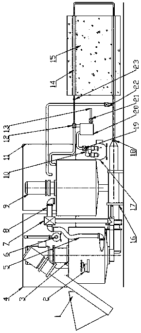
[0015] like figure 1 As shown, this embodiment includes an auger feeder 1, a load cell 2, a push-type high-speed circulation system 3, a water tank 4, a slurry return pipe 5, a water pump 6, a three-way reversing valve 7, a slurry outlet 8, a low-speed Mixing barrel system 9, sewage outlet 10, electrical control system 11 three-way vacuum valve 12, sewage outlet 13, slurry return pipe 14, prestressed beam 15, screw pump 16, vacuum pump 17, slurry outlet 18, air intake valve 19, Vacuum tank 20, blowdown valve 21, mud special overflow valve 22, slurry return port 23, and data storage and transmission system, the system realizes fully automatic pulping, guarantees the quality of slurry, and at the same time the slurry output and holding pressure It is stable and can detect the amount of grouting to ensure that the grout in the tunnel is full, automatically record the data of the grouting process, the system has a high degree of automation, and reduces the uncertainty of manual in...


PUM


Abstract

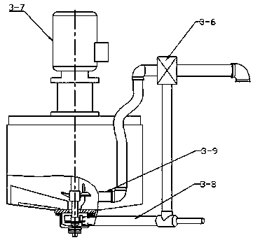
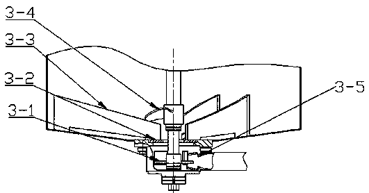
The invention relates to an intelligent vacuum circulating propulsion grouting system. A slurry outlet of a high-pressure agitation circulating system is lower than the bottom of a low-speed mixing barrel system; the installation position of a propulsion type high-speed mixing circulation system is lower than that of the low-speed mixing barrel system, and mud is conveyed out by an impeller pump in the propulsion type high-speed mixing circulation system; a rotating shaft of a disc turbine is vertically supported upward on the upper side and the lower side of an impeller pump casing, and the position, higher than the disc turbine, of the rotating shaft is fixedly provided with a propulsion type high-speed mixer; and a plurality of spoilers distributed radially are fixedly arranged on a conical bottom inside the impeller pump casing. The intelligent vacuum circulating propulsion type grouting system has the advantages that the installation height of the propulsion high-speed mixing circulation system is lowered, the high-speed rotation is stable, the measurement precision of a weighing sensor is high, and the maintenance and cleaning is convenient; the automatic pulping is achieved,the quality of slurry is ensured, the grouting output and the dwell pressure are stable, the amount of grouting can be detected to ensure full slurry in tunnel and data of the grouting process is automatically recorded; and the degree of automation is high, and the quality of projects is improved.

Description

technical field [0001] The invention relates to the technical field of prestressed stirring, in particular to an intelligent vacuum circulation propulsion grouting system. Background technique [0002] In the traditional vacuum circulation grouting system, the position of the high-speed mixing tank must be higher than that of the low-speed mixing tank, so as to ensure that the mud prepared by the high-speed mixing tank can flow into the low-speed mixing tank by the weight of the mud. The high-speed barrel is stirred at a high position. Under high-speed rotation, the shaking force is large, causing instability, making the measurement accuracy of the load cell poor, and maintenance and cleaning are inconvenient; Guaranteed, it is inconvenient to observe, the stroke of the feeding machine is also longer, the difficulty of manufacturing is increased, the degree of deformation is difficult to control, the life and durability are reduced, and the cost is also increased. Contents...

Claims


Application Information

Patent Timeline
Patent Type & Authority Applications(China)
IPC IPC(8): B28C9/02B28C5/16B28C5/08B28C7/02B28C7/04
Inventor 李建强邓国泉王婷杨帆梁苡铭李伯灿
Owner 柳州泰姆预应力机械有限公司
Learn More