
A high-current high-voltage vacuum diode

A vacuum diode and high-voltage technology, which is applied in the field of high-current vacuum diodes and high-voltage high-voltage vacuum diodes, can solve the problems of shortened life, reduced withstand voltage of vacuum diodes, flashover along the surface, etc., and achieves reduced surface field strength and uniform electric field distribution , Increase the effect of creepage distance

Active Publication Date: 2022-05-03
NAT UNIV OF DEFENSE TECH
View PDF2 Cites 0 Cited by
  • Summary
  • Abstract
  • Description
  • Claims
  • Application Information

AI Technical Summary

Problems solved by technology

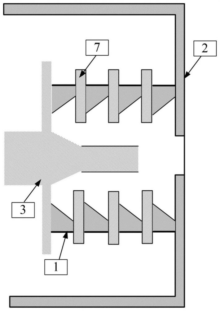
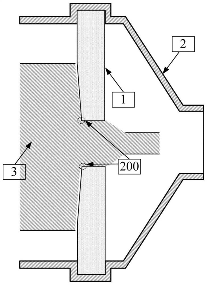
[0013] The technical problem to be solved by the present invention is to solve the phenomenon that the vacuum diode insulator in the high-current electron beam accelerator is prone to flashover along the surface, and the electron beam under the guidance of the magnetic field is easy to flow back along the magnetic force line and bombard the cathode, which leads to the reduction of the withstand voltage of the vacuum diode and the shortening of the service life. A high-current high-voltage vacuum diode designed in combination with a long tapered hollow structure insulator and a shielding ring

Method used


Image

  • A high-current high-voltage vacuum diode
  • A high-current high-voltage vacuum diode
  • A high-current high-voltage vacuum diode

Examples


Embodiment Construction

[0048] The present invention will be further described below in conjunction with the accompanying drawings.

[0049] Such as image 3 As shown, the present invention is composed of an insulator 1, an anode 2, a cathode 3, a shielding ring 4, a flange 5, and a sealing ring 6. The cathode 3, the shielding ring 4, the insulator 1, and the anode 2 are coaxially nested from the inside to the outside, and the insulator The outer edge of 1 is tightly pressed against the inner wall of the anode 2 through the flange 5 and the sealing ring 6, and the cathode 3 passes through the hollow part of the insulator 1 and is connected with the high-power pulse driving source 100 of the previous stage. The end connected to the high-power pulse driving source 100 of the present invention is defined as the left end, and the end connected to the microwave source 102 of the present invention is defined as the right end. The shielding ring 4 is screwed on the right end of the cathode 3 through metal ...


PUM

PropertyMeasurementUnit
diameteraaaaaaaaaa
thicknessaaaaaaaaaa
diameteraaaaaaaaaa

Abstract

The invention discloses a high-current high-voltage vacuum diode, and aims to solve the problem that a vacuum diode insulator is prone to flashover along the surface. The invention is composed of an insulator, an anode, a cathode, a shielding ring, a flange, and a sealing ring. The cathode, the shielding ring, the insulator, and the anode are coaxially nested from the inside to the outside, and the outer edge of the insulator is tightly pressed on the inner wall of the anode through the flange and the sealing ring. , the shielding ring is screwed on the right end of the cathode; the anode is grounded, and there is an air hole on the side, and the air hole is externally connected to the vacuum unit. The insulator is a long tapered hollow structure, which isolates the medium area of ​​the high-power pulse drive source from the vacuum area in the anode cylinder, and the hollow part of the insulator is inserted with a cathode. The shielding ring is a disc-shaped metal structure with a round tube, which is composed of a round tube, a disc, and a cylinder. The shielding ring can block a part of the electron beam that flows back along the magnetic force line, and prevent the electron beam from bombarding the surface of the insulator. The invention solves the problem that the vacuum diode insulator is easy to produce flashover along the surface, and the electron beam is easy to flow back along the magnetic force line and bombard the cathode under the guidance of the magnetic field.

Description

technical field [0001] The invention relates to a high-current vacuum diode, in particular to a high-current high-voltage vacuum diode with a radial insulation structure, which belongs to the field of pulse power. Background technique [0002] Pulse power technology is a new science and technology developed due to the needs of national defense research. In the past 40 years, with the development and improvement of various types of high-current electron beam accelerators, pulse power technology has developed rapidly and has become one of the most active high-tech in the world. At present, through the high-current electron beam accelerator, it has been possible to generate electron beam currents of several MeV and tens of megaamperes in a short period of time (tens to hundreds of nanoseconds). Applications in other fields are also becoming more and more prominent. [0003] In the high-current electron beam accelerator, the vacuum diode is a component that converts the high-v...

Claims


Application Information

Patent Timeline
Patent Type & Authority Patents(China)
IPC IPC(8): H01J19/44H01J19/54H01J21/04
CPCH01J19/44H01J19/54H01J21/04
Inventor 杨建华陈绒程新兵文建春周相钱宝良耿玖源
Owner NAT UNIV OF DEFENSE TECH
Learn More