Emergency communication antenna automatic deployment and real-time monitoring system

An emergency communication and real-time monitoring technology, which is applied to antennas, folding antennas, antenna supports/installation devices, etc., can solve problems such as low work efficiency, and achieve the effect of improving work efficiency and improving the adjustment angle

Active Publication Date: 2022-07-22
NANJING IRONHORSE INFO TECH CO LTD
View PDF4 Cites 0 Cited by
  • Summary
  • Abstract
  • Description
  • Claims
  • Application Information

AI Technical Summary

Problems solved by technology

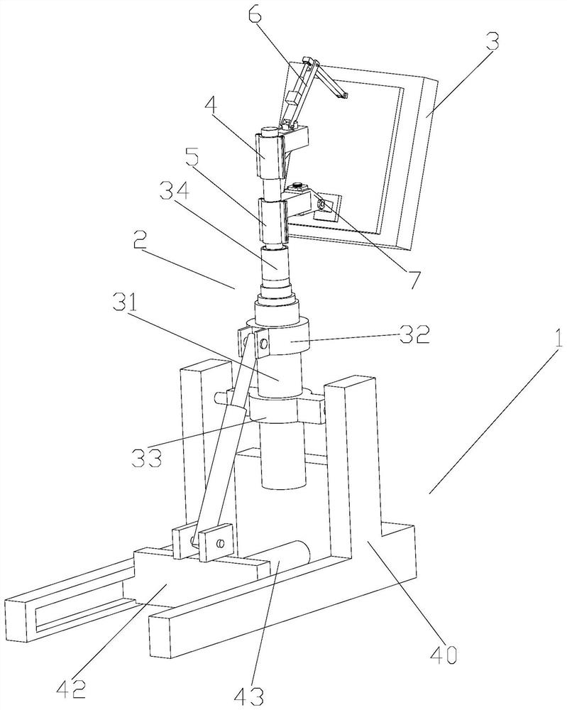
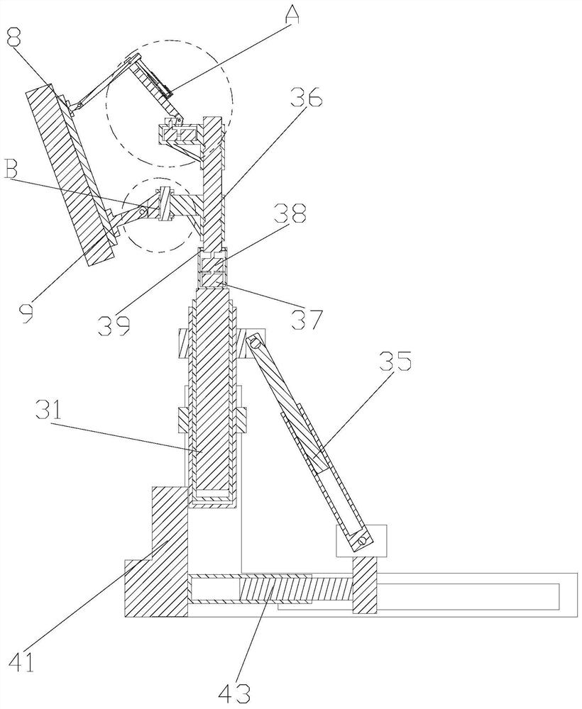
[0003] The purpose of the present invention is to provide an automatic deployment and real-time monitoring system for emergency communication antennas, which aims to solve the problem that most of the existing security work in the prior art uses manual adjustment of the positions of emergency communication antennas. In order to make the coverage of emergency communication antennas reach In an ideal state, it is necessary to manually adjust the position of the emergency communication antenna, which is a technical problem with low work efficiency.

Method used


Image

  • Emergency communication antenna automatic deployment and real-time monitoring system
  • Emergency communication antenna automatic deployment and real-time monitoring system
  • Emergency communication antenna automatic deployment and real-time monitoring system

Examples


Embodiment Construction

[0020] The following describes in detail the embodiments of the present invention, examples of which are illustrated in the accompanying drawings, wherein the same or similar reference numerals refer to the same or similar elements or elements having the same or similar functions throughout. The embodiments described below with reference to the accompanying drawings are exemplary, and are intended to explain the present invention and should not be construed as limiting the present invention.

[0021] In the description of the present invention, it should be understood that the terms "length", "width", "upper", "lower", "front", "rear", "left", "right", "vertical", The orientations or positional relationships indicated by "horizontal", "top", "bottom", "inside", "outside", etc. are based on the orientations or positional relationships shown in the accompanying drawings, which are only for the convenience of describing the present invention and simplifying the description, rather...


PUM


Abstract

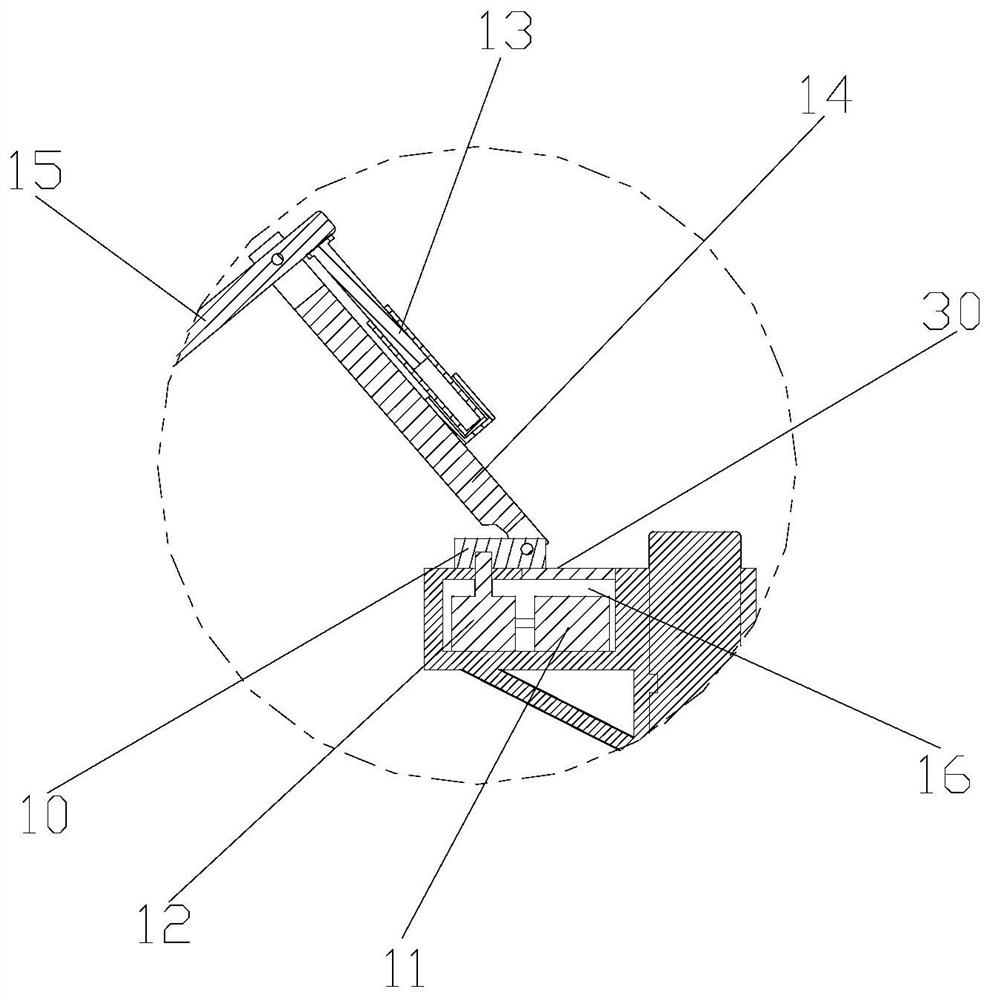
The invention discloses an emergency communication antenna automatic deployment and real-time monitoring system. The first motor and the first electric push rod are both electrically connected with the main controller. When the wireless coverage of the emergency communication antenna decreases, the main controller controls the first motor to start, so as to drive the rotating base to rotate through the first reduction box, so that the emergency communication antenna is horizontally driven. Rotate in the direction, start the first electric push rod, and drive the second folding arm to extend through the first electric push rod, so as to control the inclination angle of the emergency communication antenna and further improve the adjustment angle of the emergency communication antenna , so that the network achieves an ideal wireless coverage state, and by using the main controller to control the operation of the first motor and the electric push rod, instead of manually adjusting the position of the emergency communication antenna, the work efficiency is greatly improved.

Description

technical field [0001] The invention relates to the technical field of emergency communication equipment, in particular to an automatic deployment and real-time monitoring system for emergency communication antennas. Background technique [0002] With the continuous development of economic level, major cities hold various exhibitions, concerts, competitions and other activities with large numbers of people gathering more and more frequently. In this case, major mobile communication network operators Generally, a large amount of resources are invested in on-site communication guarantee work. Most of the existing guarantee work adopts manual adjustment of the position of the emergency communication antenna. In order to make the coverage rate of the emergency communication antenna reach an ideal state, it is necessary to manually adjust the emergency communication antenna. location, work efficiency is low. SUMMARY OF THE INVENTION [0003] The purpose of the present inventio...

Claims


Application Information

Patent Timeline
Patent Type & Authority Patents(China)
IPC IPC(8): H01Q1/12H01Q1/10H01Q3/08
CPCH01Q1/12H01Q1/10H01Q3/08
Inventor 林征
Owner NANJING IRONHORSE INFO TECH CO LTD
Why Eureka
Try Eureka