Valve capable of being precisely adjusted

A precision adjustment and valve technology, applied to valve details, valve devices, cocks including cut-off devices, etc., can solve problems such as poor accuracy, poor stability of bellows, and affecting the bonding effect of rubber strips, and achieve the adjustment of water flow speed Convenient and fast, accurate and stable water flow rate, convenient and fast installation and disassembly

Active Publication Date: 2020-10-27
响水县正宇工具有限公司
View PDF8 Cites 0 Cited by
  • Summary
  • Abstract
  • Description
  • Claims
  • Application Information

AI Technical Summary

Problems solved by technology

[0003] However, most of the valves connected to the bellows are installed on the side wall of the water tank, and it is easy to wet the operator when adjusting the water flow rate. At the same time, the accuracy of the adjustment is relatively poor, which is not convenient for quick adjustment. At the same time, the stability of the bellows is poor. After connecting with the valve, it is also easy to touch and bend under the change of water pressure, which makes the effect of cooling spray less. The bonding effect of the strip, when the water flow is small, the cooling effect on the rubber strip and the pressure wheel is poor, and the rubber strip is easily bonded to the pressure wheel, which affects the extrusion molding effect of the pressure wheel on the winding tube

Method used


Image

  • Valve capable of being precisely adjusted
  • Valve capable of being precisely adjusted
  • Valve capable of being precisely adjusted

Examples


Embodiment Construction

[0027] In order to make the technical means, creative features, goals and effects achieved by the present invention easy to understand, the present invention will be further described below in conjunction with specific embodiments.

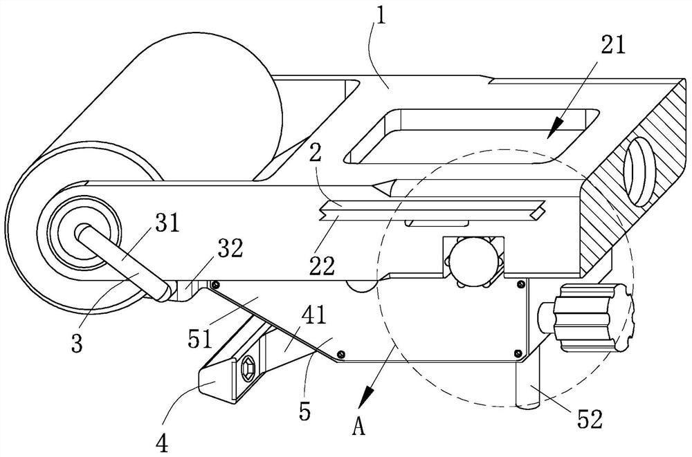
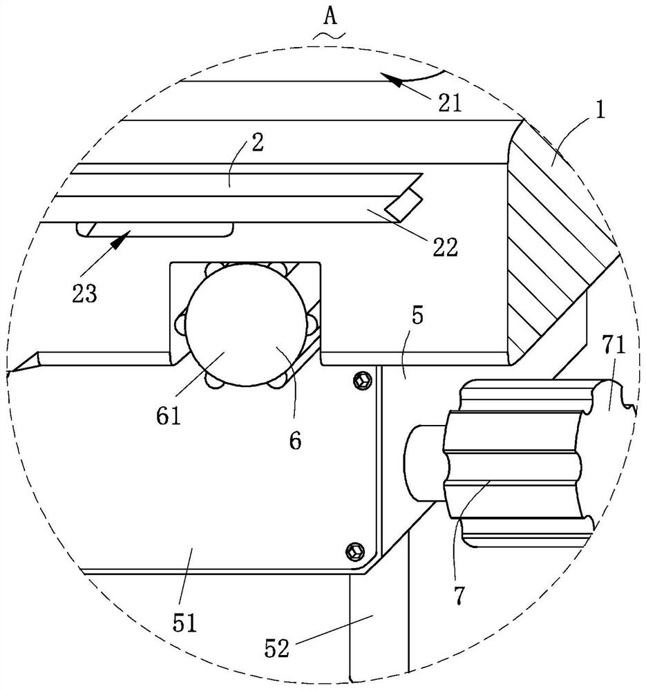
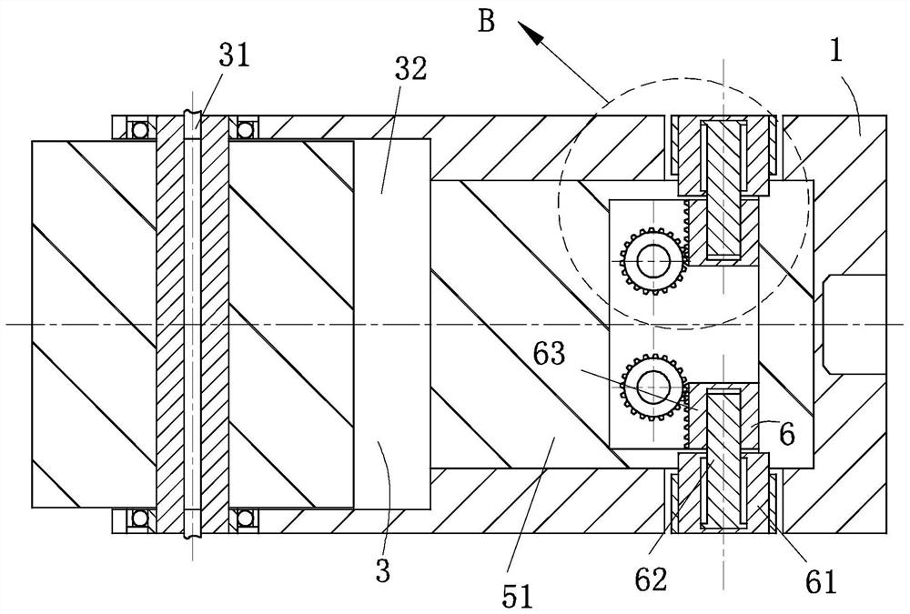
[0028] like Figure 1-Figure 9 As shown, a valve that can be precisely adjusted according to the present invention includes a pressure wheel carriage 1, a sealing structure 2, a chip removal structure 3, a spray structure 4, a valve structure 5, a flow rate control structure 6 and an angle adjustment structure 7 The pressure roller carriage 1 is provided with the sealing structure 2 for protecting the bolts on the valve structure 5, the sealing structure 2 is detachably connected to the pressure roller carriage 1, and is used for The valve structure 5 for controlling the flow rate of the water flow is detachably connected to the roller carriage 1; the valve structure 5 is provided with the flow rate control structure 6 for controlling the flow rat...


PUM


Abstract

The invention relates to the field of valves, in particular to a valve capable of being precisely adjusted. The valve comprises a pressing wheel sliding frame, a sealing structure, a scrap removing structure, a spraying structure, a valve structure, a flow speed control structure and an angle adjusting structure; the valve structure is provided with the flow speed control structure used for controlling the water flow speed; the valve structure is provided with the spraying structure used for spraying and cooling the formed winding pipe, and the angle adjusting structure used for adjusting theangle of the spraying structure is arranged in the valve structure, so that the spraying speed of the spraying structure on the pipeline is conveniently controlled through the flow speed control structure, and the adjustment of the water flow speed is more convenient and faster; and meanwhile, the flow speed of the adjusted water flow is more accurate and stable, the angle between the spraying structure and the valve structure can be conveniently adjusted through the angle adjusting structure, so that the spraying structure is suitable for pipelines of different sizes, the cooling effect of the spraying structure on the pipelines is greatly improved, and the forming quality of the pipelines is improved.

Description

technical field [0001] The invention relates to the field of valves, in particular to a valve capable of precise adjustment. Background technique [0002] Valves are pipeline accessories used to open and close pipelines, control flow direction, adjust and control the parameters (temperature, pressure and flow) of the conveying medium. According to their functions, they can be divided into shut-off valves, check valves, regulating valves, etc. The pressure relief valve is composed of needle valve, pressure gauge, main valve, pilot valve and connecting pipe, etc. It can be opened and closed automatically according to the working pressure of the system. It is generally installed on the equipment or pipeline of the closed system to protect the safety of the system, for example: In the production process of the winding pipe, the valve and the bellows are used to spray and cool the pressure roller to prevent the material from sticking to the pressure roller and to make the forming...

Claims


Application Information

Patent Timeline
Patent Type & Authority Applications(China)
IPC IPC(8): B29C53/56B29C53/80B29C53/84F16K5/06F16K31/50F16K31/54B08B1/02
CPCB08B1/005B08B1/02B29C53/566B29C53/8008B29C53/845F16K5/0647F16K31/502F16K31/508F16K31/54
Inventor 不公告发明人
Owner 响水县正宇工具有限公司
Why Eureka
Try Eureka