
Automobile seat and angle adjuster design method

A technology for car seats and recliners, which is applied to movable seats and other directions, can solve the problems of poor comfort, hysteresis of recliner adjustment, large torque difference, etc., and achieves reasonable and reliable structural design and simple manufacturing process. , the effect of strengthening the bearing strength

Inactive Publication Date: 2019-01-01
安徽金诚汽车装饰设计开发有限公司
View PDF5 Cites 0 Cited by
  • Summary
  • Abstract
  • Description
  • Claims
  • Application Information

AI Technical Summary

Problems solved by technology

There are the following disadvantages in its use: 1. There is a sense of hysteresis when the recliner is reversing and adjusting, especially when the motor-driven continuous recliner is used, when the seat back is adjusted from one direction to the opposite direction, the backrest adjustment response is not sensitive, When adjusting the delay, the human body will feel the gap period of the backrest adjustment, which will affect the driving experience of the human body
2. The durability of the above-mentioned recliner is not enough. In the process of rotating friction, due to the limited bearing area of ​​the wedge-shaped block in the recliner, when there is a slight change in size, the space posture that the wedge-shaped block can adapt to eliminate the gap is limited, which will lead to The recliner clearance is not completely eliminated, which will bring a series of problems such as abnormal noise and vibration of the seat
However, it still has the disadvantages mentioned in CN2012101407425 when it is in use, and also has the following disadvantages: due to the asymmetric design adopted, when a certain load is applied on the seat back, the driving part drives the cam and the wedge respectively (ie Forward rotation and reverse rotation) The torque difference is large, and the comfort during use is poor

Method used

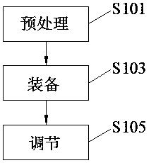

Image

  • Automobile seat and angle adjuster design method
  • Automobile seat and angle adjuster design method
  • Automobile seat and angle adjuster design method

Examples


Embodiment Construction

[0026] The following will clearly and completely describe the technical solutions in the embodiments of the present invention with reference to the accompanying drawings in the embodiments of the present invention. Obviously, the described embodiments are only some, not all, embodiments of the present invention. All other embodiments obtained by persons of ordinary skill in the art based on the embodiments of the present invention belong to the protection scope of the present invention.

[0027] According to an embodiment of the present invention, a car seat and a recliner are provided.

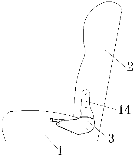
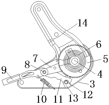
[0028] like Figure 1-2 As shown, the car seat and the recliner according to the embodiment of the present invention include a bottom pad 1 and a backrest 2 on one side of the bottom pad 1, and the two sides of the bottom pad 1 are respectively provided with substrates 3, and the substrate 3 It is a cavity structure, and the substrate 3 is fixedly connected with the bottom pad 1 by bolts. Th...


PUM


Abstract

The invention discloses an automobile seat and angle adjuster design method, the automobile seat and the angle adjuster comprise a base pad and a backrest on one side of the base pad, wherein two sides of the base pad are respectively provided with a substrate, the substrate is of a cavity structure, and the substrate is fixedly connected with the base pad through bolts, and a rotating shaft arranged horizontally is inserted on one side of the base pad. The invention discloses an integrated assembly, not only can the assembly clearance brought by the traditional angle adjuster be eliminated, and the structural design is reasonable and reliable, the substrate is connected with the connecting piece and the clamp teeth, the adjusting angle and the bearing strength of the angle adjuster can beimproved to a great extent, through the self-locking force of the gear and the two-way clamping position of the fastening piece and the limiting piece, the convenient adjustment is facilitated, but also further the bearing strength is strengthened, the hysteresis feeling of the traditional angle adjuster commutation adjustment is eliminated, the driving experience is more comfortable, and the manufacturing process is simple and the cost is low, so that the present industrial production demand can be met.

Description

technical field [0001] The invention relates to the technical field of automobiles, in particular to a method for designing an automobile seat and a recliner. Background technique [0002] The car seat continuous recliner is a component installed on the car seat to realize the continuous and uninterrupted adjustment of the backrest angle of the car seat. [0003] The car seat continuous recliner currently on the market mainly adopts the principle of one-tooth difference planetary gear transmission, and mainly has the following two structures: [0004] The first structure, such as CN2012101407425, is disclosed in the invention patent application of "a car seat recliner with one-tooth difference planetary gear internal meshing". It uses a spring to tighten the two wedge blocks to eliminate the radial gap. Its main features are : Two wedge-shaped blocks are located in the cavity formed by the shaft sleeve and the hole-turning boss, one side of the wedge-shaped block is in co...

Claims


Application Information

Patent Timeline
IPC IPC(8): B60N2/22
CPCB60N2/22
Inventor 孟先峰
Owner 安徽金诚汽车装饰设计开发有限公司
Learn More