Adjustable precision steel forging vise

An adjustable and precise technology, applied in vices, manufacturing tools, etc., can solve the problems of affecting the size and stability of the workpiece clamped by the vice, occupying the depth resources of the throat of the vice, and the thread cannot be repaired and replaced, and achieves a compact structure. , the effect of optimizing mechanical properties and reducing welding costs

Active Publication Date: 2014-08-06
LAIZHOU HONGYUAN BENCH VICE MFR
View PDF7 Cites 1 Cited by
  • Summary
  • Abstract
  • Description
  • Claims
  • Application Information

AI Technical Summary

Problems solved by technology

Since the screw rod is set above the guide rod, it occupies the throat depth resources of the vise, which affects the size and stability of the workpiece clamped by the vise
In addition, the channel steel used for the protective screw rod is added, which not only wastes materials, but also increases the cost of manual production and welding, and also weakens the depth of the throat of the vise.
[0005] (2) The thread that is screwed with the screw to generate the clamping force is directly arranged on the fixed pliers body, that is, the nut and the fixed pliers body are designed in one piece, which will cause the disadvantage that the thread cannot be repaired and replaced after the thread is damaged. Damage will lead to the fatal flaw of scrapping the entire vise
[0008] (5) The spring is assembled on the head of the screw rod and at the front end of the movable pliers, which not only causes too much space for assembling the spring, inconvenient assembly, but also weakens the strength of the movable pliers

Method used


Image

  • Adjustable precision steel forging vise
  • Adjustable precision steel forging vise
  • Adjustable precision steel forging vise

Examples


Embodiment Construction

[0037] The present invention will be further described in detail below in conjunction with the accompanying drawings and specific embodiments.

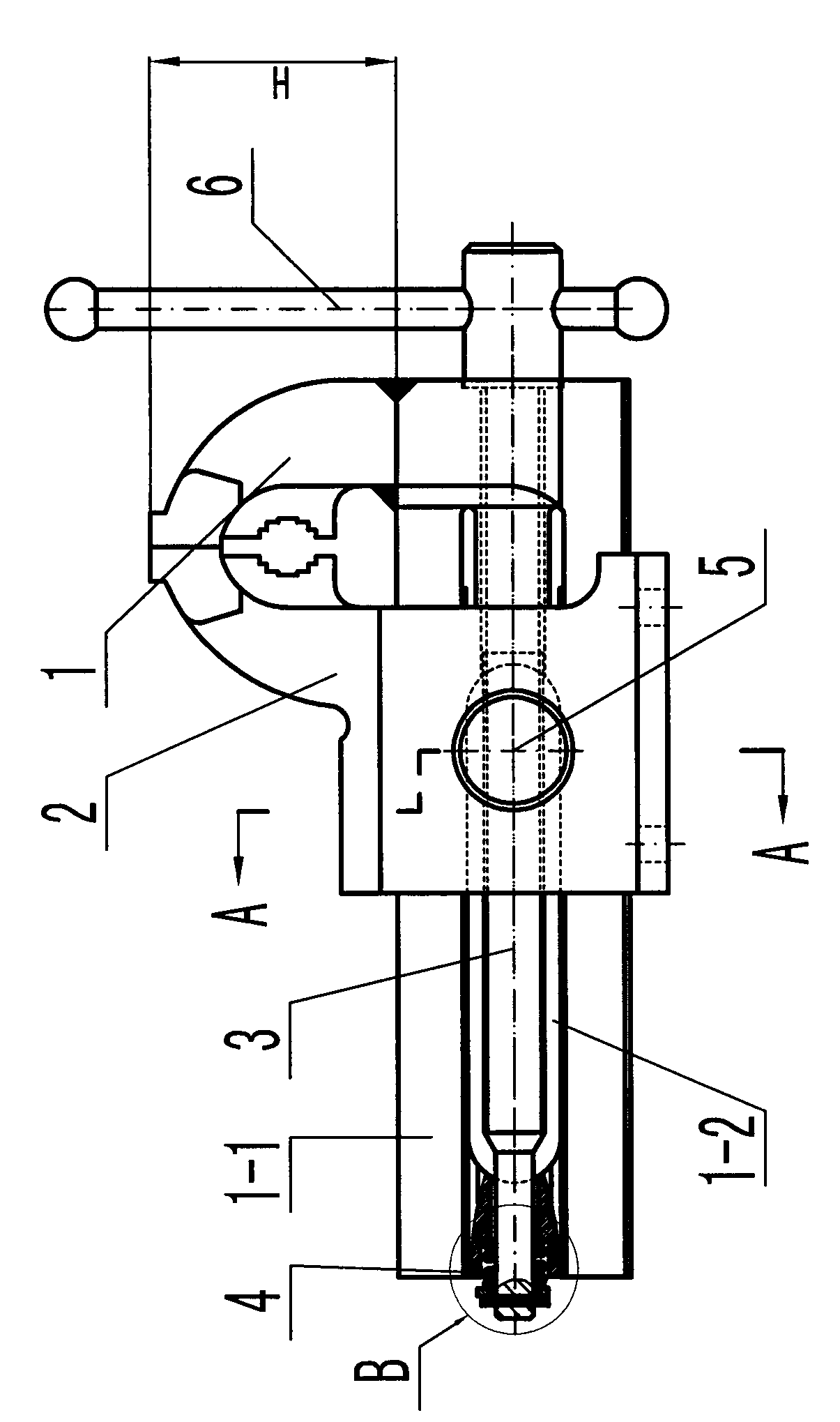
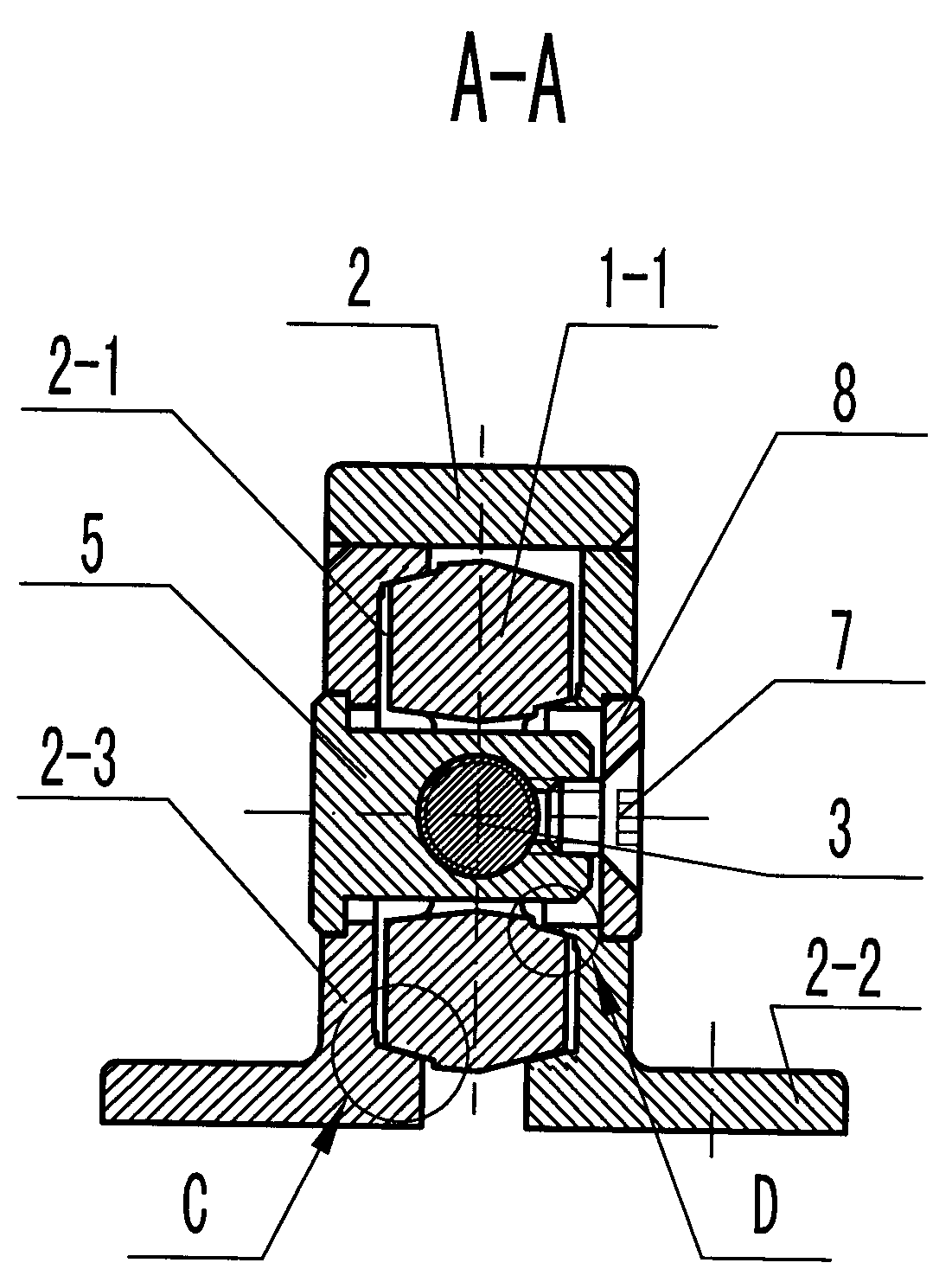
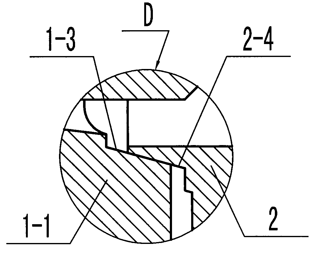
[0038] Depend on Figure 1 to Figure 3 It can be seen that the adjustable precision forged steel vise of the present invention includes a movable pliers body 1, a fixed pliers body 2, a screw rod 3, a guide rod 1-1, a nut 5, a driving rod 6, a countersunk socket head cap screw 7, a pressure plate 8, and a spring 4, of which:

[0039] figure 1 Shown is the front appearance of the present invention. Both the movable pliers body 1 and the fixed pliers body 2 are welded components and forged from steel, so the pliers body has the advantages of light weight, high strength, and convenient transportation.

[0040] The left and right sides of the fixed pliers body 2 are oppositely provided with a fixed pliers body side panel 2-3, and the bottom of the fixed pliers body side panel 2-3 is fixedly connected with two separate parts of the base...


PUM


Abstract

The invention discloses an adjustable precision steel forging vise which comprises a fixed vise body, a movable vise body, a screw, a nut, a pressing plate and a hexagon socket countersunk screw. The fixed vise body and the movable vise body are both in a component welding structure and are both made by forging steel. The movable vise body is provided with a guide rod which is provided with an elongated groove provided with the screw. The nut matched with the screw is mounted on the fixed vise body, and the pressing plate is tightened by the hexagon socket countersunk screw to be mounted at the end of the nut. A pair of outer guide rails and a pair of inner guide rails are arranged on the left sides and the right sides of the guide rod and the fixed vise body respectively, and the two pairs of guide rails are in a left-right asymmetric guide structure. The adjustable precision steel forging vise has the advantages that gaps among the guide rails are adjustable, the vise bodies are large in laryngeal size, clamping range of jaws is large, guide precision is high, and the vise bodies are high in strength and light in weight; the quick-wear part nut is more convenient to replace and maintain; and even stress on two sides of a workpiece can be achieved when the vise clamps the workpiece, and accordingly self-strength of the guide rod is given to full play, clamping force of the vise is increased, and the like.

Description

technical field [0001] The invention relates to the technical field of fitter clamping tools, in particular to an adjustable precision forged steel vise. Background technique [0002] Adjustable precision forged steel vise is a clamping tool for fitters, mainly used for fixing workpieces during machining by fitters. [0003] The structure of existing adjustable precision forged steel vise and the deficiencies thereof are as follows: [0004] (1) The screw rod is arranged above the guide rod, and a channel steel for protecting the screw rod is arranged above the guide rod. Since the screw rod is arranged above the guide rod, the throat depth resources of the vise are occupied, which affects the size and stability of the workpiece clamped by the vise. In addition, the channel steel used for the protective screw rod is increased, which not only wastes materials, but also increases the cost of manual production and welding, and also weakens the depth of the throat of the vise....

Claims


Application Information

Patent Timeline
Patent Type & Authority Patents(China)
IPC IPC(8): B25B1/02B25B1/10B25B1/24
Inventor 赵书俊王晓东迟志远李茂斗吴林涛
Owner LAIZHOU HONGYUAN BENCH VICE MFR
Why Eureka
Try Eureka