Gain control circuit

A gain control circuit and gain resistor technology, applied in gain control, amplification control, electrical components, etc., can solve the situation where the input signal and output signal are not isolated, the gain segment of the ASIC is rough, and the fine gain adjustment is not applicable. and other problems, to achieve the effect of isolation processing, wide application value, and amplification or attenuation.

Pending Publication Date: 2021-05-07
航天科工惯性技术有限公司
View PDF0 Cites 0 Cited by
  • Summary
  • Abstract
  • Description
  • Claims
  • Application Information

AI Technical Summary

Problems solved by technology

However, in this type of signal conversion mode, the gain segmentation of the ASIC is rough, which is not suitable for occasions that require fine gain adjustment; and the input signal and output signal are not isolated, so it is not suitable for occasions that require signal isolation

Method used


Image

  • Gain control circuit
  • Gain control circuit

Examples


Embodiment Construction

[0035] In order to illustrate the present invention more clearly, the present invention will be further described below in conjunction with preferred embodiments and accompanying drawings. Similar parts in the figures are denoted by the same reference numerals. Those skilled in the art should understand that the content specifically described below is illustrative rather than restrictive, and should not limit the protection scope of the present invention.

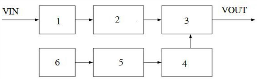
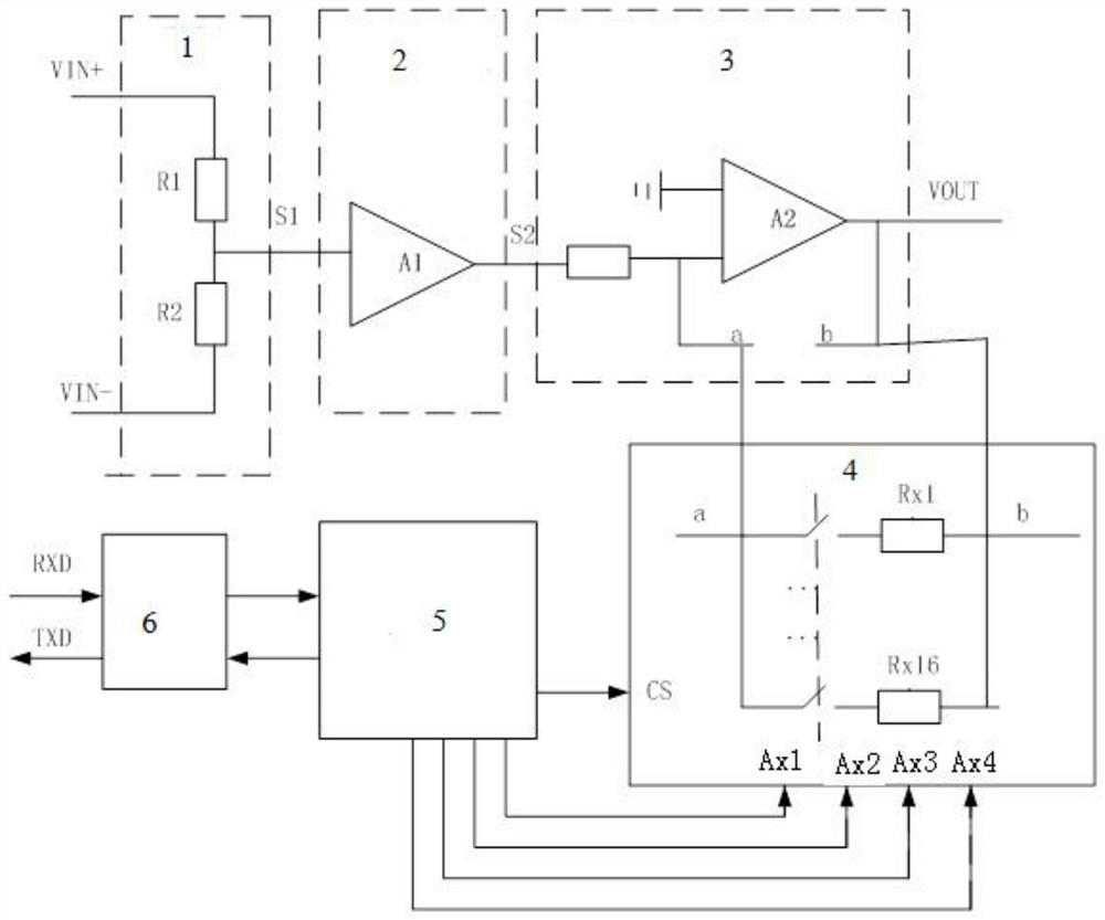
[0036] Such as figure 1 and figure 2 As shown, this embodiment relates to a gain control circuit, including:

[0037] The input terminal VIN+ and VIN- of the input level signal, the resistance voltage dividing unit 1 connected to the input terminal VIN, the signal isolation processing unit 2 connected to the resistance voltage division unit 1, and the gain connected to the signal isolation processing unit 2 Regulating unit 3.

[0038] The gain adjustment unit 3 includes an operational amplifier A2, a gain resistor cont...


PUM


Abstract

The invention discloses a gain control circuit. The circuit comprises an input end; a resistance voltage dividing unit which is used for attenuating based on an input signal and outputting a level signal; a signal isolation processing unit which outputs a gain signal based on the input level signal, wherein the output gain signal is isolated from the input level signal; a gain adjusting unit which is used for further gaining and outputting the input gain signal based on an external instruction; and an output end. The circuit realizes fine gain control of an input signal, amplification or attenuation of the intensity of the input signal, and isolation processing of an output signal and the input signal at the same time, so that the gain control circuit can be used in an application occasion needing isolation, the application scenario of the gain control circuit is expanded, and the method has a higher application value.

Description

technical field [0001] The invention relates to the technical field of electronic circuits. More specifically, it relates to a gain control circuit. Background technique [0002] For different input signal strengths, in order to ensure that the input dynamic range of the subsequent digital-to-analog converter ADC is neither saturated by large signal overload nor the system drops below the tolerable noise level, an ASIC is usually used to output The signal is adjusted to the optimum level. However, in this type of signal conversion mode, the gain segmentation of the ASIC is rough, which is not suitable for occasions that require fine gain adjustment; and the input signal and output signal are not isolated, so it is not suitable for occasions that require signal isolation. Contents of the invention [0003] The purpose of the present invention is to provide a gain control circuit, which can realize the fine gain adjustment of the input signal after the intensity of the inp...

Claims


Application Information

Patent Timeline
Patent Type & Authority Applications(China)
IPC IPC(8): H03G3/30
CPCH03G3/3042
Inventor 孔祥苓余莉冯涌泉高岩刘晓峰
Owner 航天科工惯性技术有限公司
Why Eureka
Try Eureka