Bone support type upper jaw rear long implant implantation guide seat based on three-dimensional printing technology

A 3D printing and supportive technology, applied in dental implants, dental restorations, medical science, etc., can solve the problems of long overall time of navigation surgery, insufficient strength of the guide plate, and errors between the design position and the actual position.

Pending Publication Date: 2021-05-11
SHANGHAI NINTH PEOPLES HOSPITAL AFFILIATED TO SHANGHAI JIAO TONG UNIV SCHOOL OF MEDICINE
View PDF0 Cites 0 Cited by
  • Summary
  • Abstract
  • Description
  • Claims
  • Application Information

AI Technical Summary

Problems solved by technology

We believe that this solution has the following problems: 1. Other incisions are required for the placement of surgical navigation and registration brackets, resulting in secondary damage; 2. Loose navigation and positioning brackets lead to errors between the design position and the actual position; 3. The overall time of navigation surgery is long, resulting in Postoperative swelling, infection, and increased intraoperative bleeding
[0005] There are also a few scholars and patents who have reported the technology of using digital design and planting guide to guide the planting operation. However, due to the limitations of design and material of the guide plate, this kind of technology is only suitable for conventional planting operations. For zygomatic implantation, the previous guide plate had defects such as insufficient strength, excessive thickness, difficulty in ensuring accurate positioning and depth control, which led to poor accuracy of implant guidance, and could not be truly applied in clinical practice.

Method used


Image

  • Bone support type upper jaw rear long implant implantation guide seat based on three-dimensional printing technology
  • Bone support type upper jaw rear long implant implantation guide seat based on three-dimensional printing technology
  • Bone support type upper jaw rear long implant implantation guide seat based on three-dimensional printing technology

Examples


Embodiment Construction

[0023] The present invention will be further described below in conjunction with the accompanying drawings and specific embodiments.

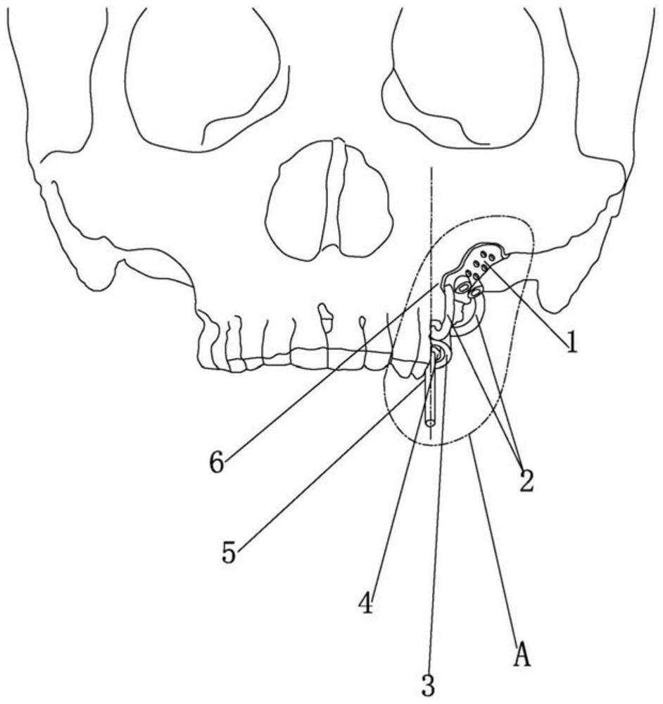
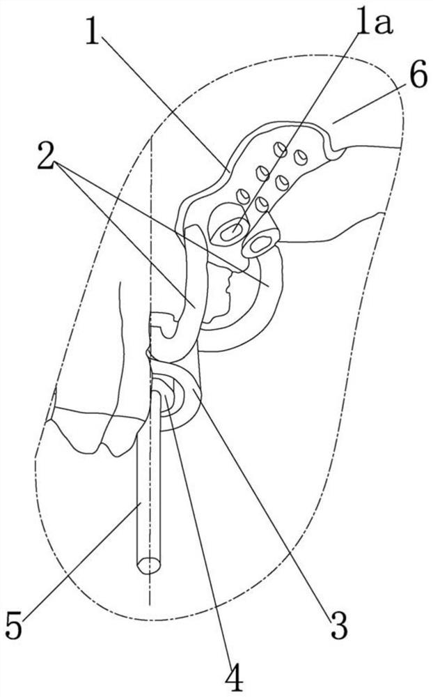
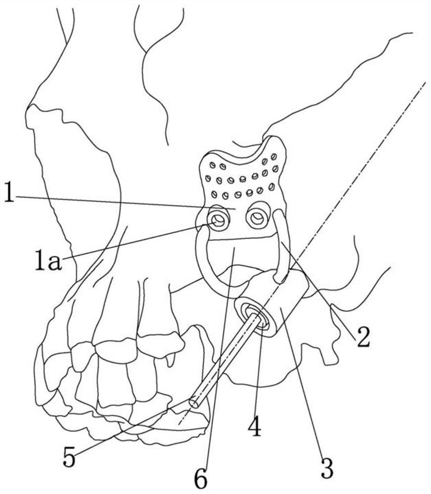
[0024] Such as Figure 1-3 As shown, the first embodiment is used for the implant surgery of the wing plate, and the bone-supported maxillary posterior long implant implant guide seat based on 3D printing technology includes:

[0025] The maxilla fixation plate 1 fits the maxilla 6 in place;

[0026] The implant guide ring part 3 is set as a circular sleeve structure and is coaxial with the implant drill needle 5. The implant guide ring part 3 is located under the maxilla 6 and faces the implant position of the maxilla 6. In this embodiment, the implant guide ring One axial end of the part 3 is facing and close to the implantation position of the maxilla 6;

[0027] The guide piece 4, the guide piece 4 is coaxially and detachably inserted into the planting guide ring part 3, and has an axially penetrating hole that accommodates the planting b...


PUM


Abstract

The invention relates to the technical field of medical instruments, in particular to a bone support type upper jaw rear long implant implantation guide seat based on a three-dimensional printing technology. The guide seat comprises an upper jaw bone in-place fixing plate which is fixedly attached to the upper jaw bone, an implantation guide ring part which is arranged to be of a round sleeve structure, is coaxial with an implantation drill needle, is located below the upper jaw bone and directly faces the implantation position of the upper jaw bone, a guide piece which is coaxially and detachably inserted into the implantation guide ring part and is provided with a positioning hole which is through in the axial direction, allows the implantation drill needle to penetrate through and is matched with the penetrating implantation drill needle, and a pair of connecting rods which are integrally connected with the upper jaw bone in-place fixing plate and the implantation guide ring part, wherein the upper jaw bone in-place fixing plate, the implantation guide ring part, the guide piece and the pair of connecting rods are integrally formed. By adopting the scheme, the implantation operation can be simpler, more accurate and quicker.

Description

technical field [0001] The invention relates to the technical field of medical devices, in particular to a bone-supported maxillary posterior long implant planting guide seat. Background technique [0002] Dental implants have gradually become an important means of restoring missing teeth. With the development of dental implant technology, many patients who could not receive dental implant due to insufficient alveolar bone volume can also receive dental implant, and achieved good restoration results. Conventional dental implants in the maxillary molar area require implants with a length of at least 6-12 mm, and the process of implantation and hole preparation should avoid penetrating the maxillary sinus floor (to avoid the risk of maxillary sinus infection and implant failure). Disuse resorption and gasification of the maxillary sinus floor decrease, and the remaining alveolar bone in the maxillary molar area after tooth loss often presents a significant shortage, making it...

Claims


Application Information

Patent Timeline
Patent Type & Authority Applications(China)
IPC IPC(8): A61C8/00
CPCA61C8/0089A61C8/009
Inventor 司家文沈洪洲史俊于洪波沈国芳
Owner SHANGHAI NINTH PEOPLES HOSPITAL AFFILIATED TO SHANGHAI JIAO TONG UNIV SCHOOL OF MEDICINE
Why Eureka
Try Eureka