
A relief valve suitable for compensating hydraulic power in back pressure condition

A technology of hydraulic power and overflow valve, which is applied in the field of aerospace servo system, can solve the problems of high cost, spool reset jamming, etc., and achieve the effect of compact structure, eliminating jamming, and high precision of voltage regulation

Active Publication Date: 2021-09-28
HARBIN INST OF TECH
View PDF0 Cites 0 Cited by
  • Summary
  • Abstract
  • Description
  • Claims
  • Application Information

AI Technical Summary

Problems solved by technology

Finally, under the load sudden drop condition of the ordinary relief valve, the large thrust spring pushes the spool to reset, which often causes jamming due to vacuum, which is not allowed in the aerospace servo system
Although the above-mentioned problems can be alleviated simply by improving the machining accuracy and selecting materials with superior performance, the cost is relatively high. This patent aims to alleviate the above-mentioned problems from the perspective of optimizing the structural design

Method used


Image

  • A relief valve suitable for compensating hydraulic power in back pressure condition
  • A relief valve suitable for compensating hydraulic power in back pressure condition
  • A relief valve suitable for compensating hydraulic power in back pressure condition

Examples


Embodiment Construction

[0018] In order to enable those skilled in the art to better understand the solution of the present invention, the following in conjunction with the attached Figure 1~6 The present invention is described in further detail.

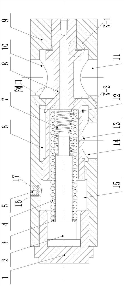
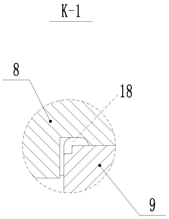
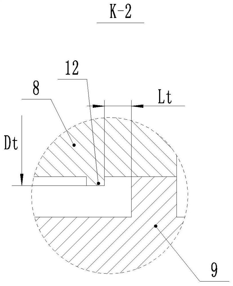
[0019] A relief valve suitable for compensating hydraulic power in working conditions with back pressure, comprising a spool 8, a valve body 9 that slides with the spool 8 and fits on the outside of the spool 8, and a spring blocked on one side of the valve body 9 The end cover 1 and the main spring 4 arranged between the spring end cover 1 and the valve core 8; the valve body 9 is provided with an inlet A11, an outlet B10, an overflow port C14 and an oil discharge port D16 for connecting the oil tank, A chamber e18, an oil chamber f6 and a spring chamber g15 are formed between the valve body 9 and the valve core 8, the overflow port C14 communicates with the oil chamber f6, and the valve core 8 and the valve body 9 are provided at the inlet end of the oi...


PUM


Abstract

The utility model relates to an overflow valve suitable for compensating hydraulic power in working conditions with back pressure, which belongs to the technical field of aerospace servo systems. The valve body is provided with an inlet A, an outlet B, an overflow port C and an oil discharge port D, and a chamber e, an oil chamber f and a spring chamber g are formed between the valve body and the valve core, and the overflow port C and The oil chamber f is connected, the valve core and the valve body are provided with a valve port at the inlet end of the oil chamber f, and a flange structure is provided at the valve core near the valve port. The stepped design, hollow design and parallel double spring design adopted by the valve core of the present invention make the valve compact in structure and have a large thrust-to-weight ratio. By setting a damping hole on the spool, the oil is replenished in time during the retraction process of the spool, which effectively eliminates the "stuck" phenomenon of the spool. By reasonably matching the throttling area of ​​the damping hole of the spool and the damping hole of the oil return port, the adverse effect of the back pressure of the overflow port on the balance of the spool is effectively eliminated.

Description

technical field [0001] The invention belongs to the technical field of aerospace servo systems, and in particular relates to an overflow valve suitable for compensating hydraulic power in working conditions with back pressure. Background technique [0002] As the pressure control element of servo energy, the relief valve is mainly used for constant pressure and relief. When used as a safety valve, it can also play the role of preventing overload and safety protection. Compared with general hydraulic systems, aerospace servo systems often have the characteristics of high pressure and large flow, which put forward higher requirements for the reliability, pressure stabilization accuracy and thrust-to-weight ratio of relief valves. Specifically, the constant pressure spring and valve core assembly of the relief valve used in the aerospace system should have a relatively large thrust-to-weight ratio, and the hydraulic power fluctuation of the valve port should be as small as poss...

Claims


Application Information

Patent Timeline
Patent Type & Authority Patents(China)
IPC IPC(8): F15B13/02
CPCF15B13/023F15B13/029
Inventor 杨庆俊李丛飞毛奇罗宁波刘钰栋姜宏暄罗小梅吕庆军
Owner HARBIN INST OF TECH
Learn More