Ignition device having power compensation function

An ignition device and power compensation technology, applied in jet propulsion device, gas turbine device, machine/engine, etc., can solve the problems of ignition device spark frequency reduction, electric energy conversion power reduction, inability to ignite oil-gas mixture steam, etc., and achieve constant spark frequency Effect

Inactive Publication Date: 2015-12-16
哈尔滨东安高精管轴制造有限公司
View PDF5 Cites 0 Cited by
  • Summary
  • Abstract
  • Description
  • Claims
  • Application Information

AI Technical Summary

Problems solved by technology

However, when the power supply voltage of the ignition device decreases, the power of electric energy conversion will decrease accordingly, which directly leads to a decre...

Method used


Image

  • Ignition device having power compensation function

Examples


Embodiment Construction

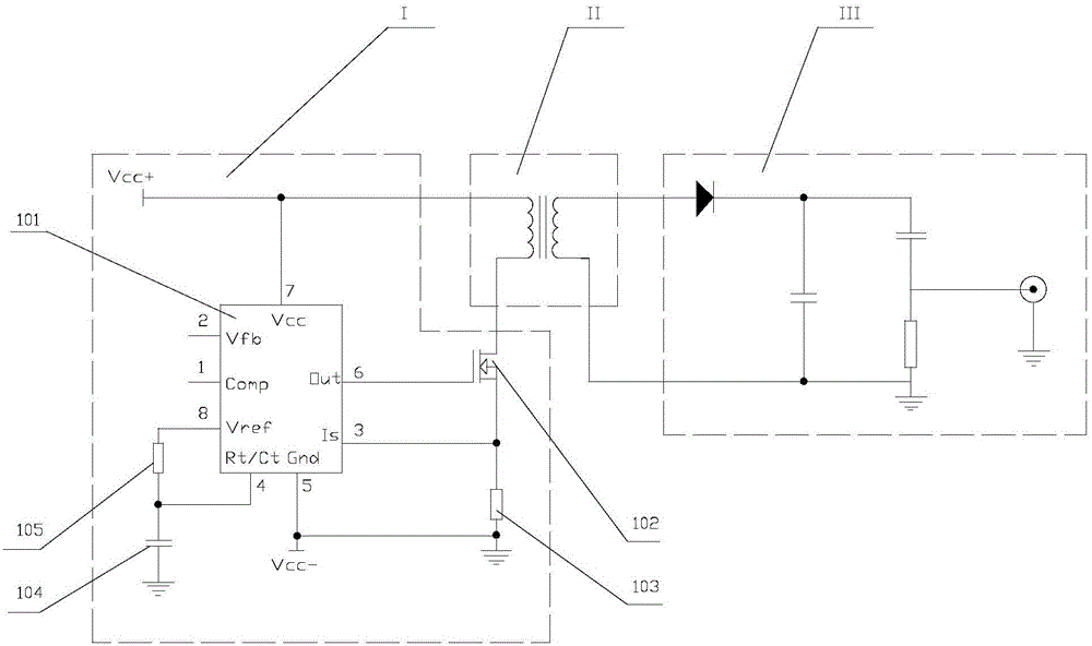
[0013] As shown in the figure, the ignition device with power compensation function includes: energy conversion circuit I, transformer II and energy storage discharge circuit III, and the power compensation function is realized by the energy conversion circuit, specifically including pulse width modulator 101, MOS tube 102, sampling resistor 103, frequency modulation capacitor 104 and frequency modulation resistor 105, pin 7 of the pulse width modulator 101 is connected to the positive pole of the power supply and one end of the primary coil of the transformer, the other end of the primary coil of the transformer is connected to the drain of the MOS tube 102, and the MOS The gate of the tube 102 is connected to pin 6 of the pulse width modulator 101, the source of the MOS tube 102 is connected to the sampling resistor 103 and grounded, and the pin 3 of the pulse width modulator 101 is connected between the source of the MOS tube 102 and the sampling resistor 103, Pin 5 is conne...


PUM


Abstract

The invention relates to an ignition device having a power compensation function. The ignition device having the power compensation function comprises an energy conversion circuit, a transformer and an energy storage discharge circuit. The power compensation function is achieved through the energy conversion circuit which specifically comprises a pulse width modulator, an MOS transistor, a sampling resistor, a frequency adjusting capacitor and a frequency adjusting resistor. A pin 7 of the pulse width modulator is connected with the positive electrode of a power source and one end of a primary coil of the transformer. The other end of the primary coil of the transformer is connected with the drain electrode of the MOS transistor. The grid electrode of the MOS transistor is connected with a pin 6 of the pulse width modulator. A pin 3 of the pulse width modulator is connected between the source electrode of the MOS transistor and the sampling resistor. A pin 5 of the pulse width modulator is connected with the negative electrode of the power source. The frequency adjusting resistor is connected between a pin 4 and a pin 8 of the pulse width modulator in series. The frequency adjusting capacitor is connected between the pin 4 of the pulse width modulator and the ground. By the adoption of the ignition device, when the power supply voltage of the power source is reduced, power-on time is prolonged through a field effect transistor till the current reaches a set value so as to compensate for the power lost due to the voltage drop, and the spark frequency output by the ignition device is constant.

Description

technical field [0001] The invention relates to an ignition device for starting an aeroengine, in particular to an ignition device with power compensation function. Background technique [0002] Ignition devices are widely used in various fields such as engines, starters, and gas turbines to ignite the oil-gas mixture in the combustion chamber. Its ignition device is to pass low-voltage direct current into the primary coil of the transformer. When the current is cut off instantly, the electric energy will be coupled to the secondary coil of the transformer and boosted. Therefore, by periodically turning on and off the primary coil current, the required high-voltage pulse can be obtained in the secondary, which breaks down the air, forms an electric spark, and realizes the ignition function. [0003] The current ignition device is mainly divided into two types: contact type and self-excited oscillation circuit type. The contact mode is to use the magnetic force generated by...

Claims


Application Information

Patent Timeline
IPC IPC(8): F02C7/266
Inventor 付洪旭贾云兰吕亚洲黄国权崔久艳刘力强池春霞王舒
Owner 哈尔滨东安高精管轴制造有限公司
Why Eureka
Try Eureka