Antenna and miniaturization method thereof

An antenna and radiator technology, applied in the field of block antenna and its miniaturization, can solve the problems of frequency reduction and antenna gain reduction.

Inactive Publication Date: 2011-06-22
HONG FU JIN PRECISION IND (SHENZHEN) CO LTD +1
View PDF3 Cites 2 Cited by
  • Summary
  • Abstract
  • Description
  • Claims
  • Application Information

AI Technical Summary

Problems solved by technology

Generally, the size of the antenna is reduced by modifying the material of the antenna. However, modifying the material of the antenna will cause the characteristics of the antenna to change, such as the antenna gain (gain) decreases, and the frequency decreases.

Method used


Image

  • Antenna and miniaturization method thereof
  • Antenna and miniaturization method thereof
  • Antenna and miniaturization method thereof

Examples


Embodiment Construction

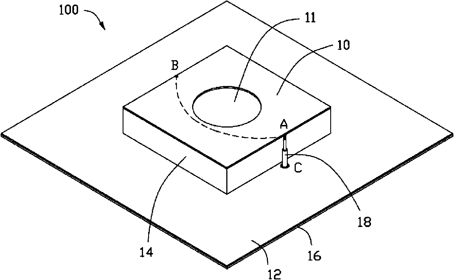
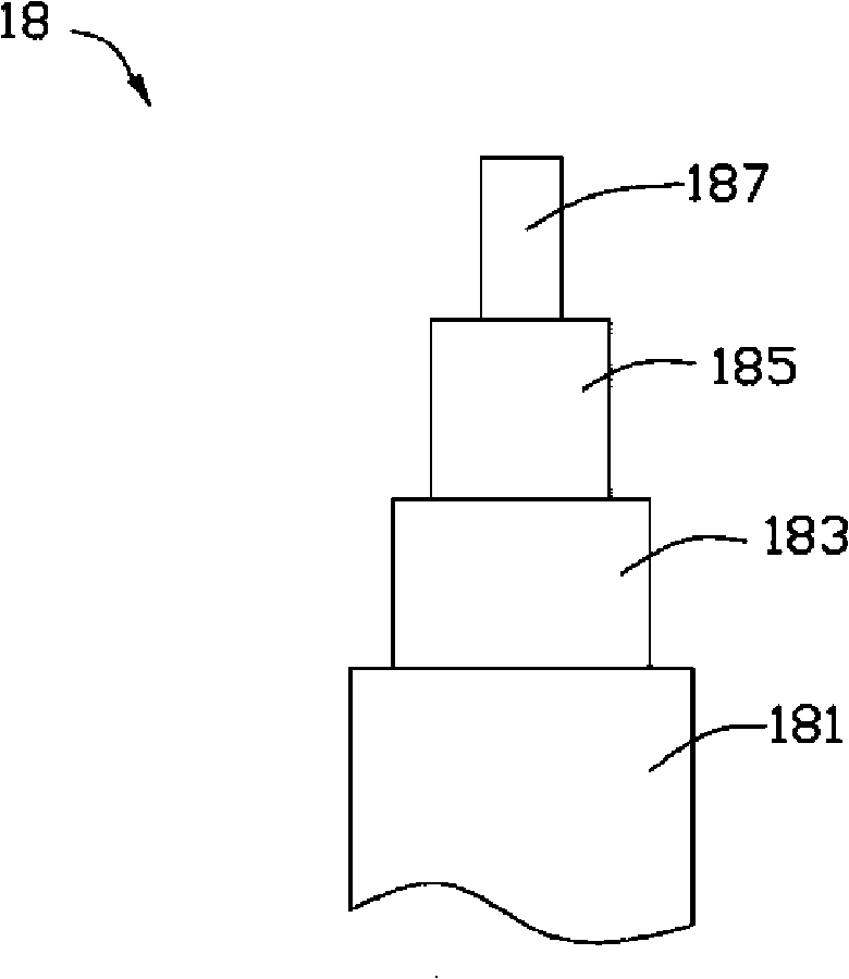
[0015] Such as figure 1 As shown, it is a schematic structural diagram of the antenna 100 in a preferred embodiment. In this embodiment, the antenna 100 is a patch antenna, also known as a patch antenna, which includes a radiator 10 , a metal layer 12 , a dielectric 14 , an insulating substrate 16 and a transmission line 18 .

[0016] The metal layer 12 is parallel to the radiator 10 , and the metal layer 12 is laid on the insulating substrate 16 and electrically grounded. In this embodiment, the material of the metal layer 12 and the radiator 10 is the same, preferably, the material of the metal layer 12 and the radiator 10 includes iron.

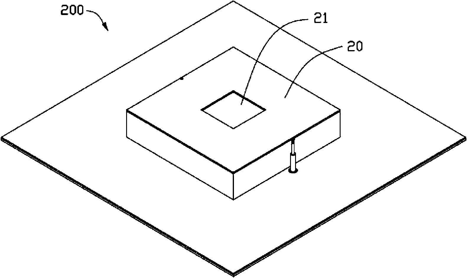
[0017] The dielectric 14 is located between the radiator 10 and the metal layer 12 , and the arrangement of the dielectric 14 makes the antenna 100 not susceptible to frequency drift caused by temperature. In this embodiment, the dielectric 14 is hollowed out, and the pattern of the hollowed out part can be a circle, a square or any othe...


PUM


Abstract

The invention relates to a miniaturization method of an antenna. The antenna comprises a radiating body. The miniaturization method of the antenna comprises the following steps: decreasing the size of the radiating body of the antenna to shorten a current path of the antenna; setting up a through hole on the radiating body to increase the current path of the antenna, wherein the shortened size for the current path of the antenna is same as the increased size for the current path of the antenna; and forming an miniaturized antenna. By using the miniaturization method of the antenna, the volume of the antenna can be reduced under the condition of keeping the current path of the antenna unchanged, thus the miniaturized antenna can keep frequency unchanged. The invention also relates to an antenna with smaller volume.

Description

technical field [0001] The invention relates to an antenna, in particular to a block antenna and its miniaturization method. Background technique [0002] Since the invention of the antenna by Hertz and Marconi, the role of the antenna in social life has been increasing day by day, and it has become an indispensable part of our life. Today's antennas are ubiquitous, and they have penetrated into all areas of our lives: computers, TVs, mobile phones, satellites, cars, aircraft, ships, etc., and the size of antennas is also developing towards miniaturization. Generally, the size of the antenna is reduced by modifying the material of the antenna. However, modifying the material of the antenna will lead to changes in the characteristics of the antenna, such as a decrease in antenna gain and a decrease in frequency. Contents of the invention [0003] In view of this, it is necessary to provide an antenna with a smaller volume. [0004] It is also necessary to provide a method...

Claims


Application Information

Patent Timeline
Patent Type & Authority Applications(China)
IPC IPC(8): H01Q1/38H01Q13/08
CPCH01Q9/0407Y10T29/49016
Inventor 杨志渊
Owner HONG FU JIN PRECISION IND (SHENZHEN) CO LTD
Why Eureka
Try Eureka