A cross-band frequency conversion antenna based on intelligent origami structure

An origami structure and cross-band technology, which is applied in the field of frequency reconfigurable antennas, can solve the problems of the influence of external bias circuit and the small frequency tuning range of antenna performance, and achieve cross-band frequency conversion, small antenna electrical length, and reduce work efficiency Effect

Active Publication Date: 2020-04-24
BEIJING INSTITUTE OF TECHNOLOGYGY
View PDF4 Cites 0 Cited by
  • Summary
  • Abstract
  • Description
  • Claims
  • Application Information

AI Technical Summary

Problems solved by technology

[0005] The purpose of the present invention is to provide a cross-band frequency conversion antenna based on an intelligent origami structure in order to solve the problems that the external bias circuit affects the performance of the antenna and the frequency tuning range is small in the traditional frequency reconfigurable antenna structure.

Method used


Image

  • A cross-band frequency conversion antenna based on intelligent origami structure
  • A cross-band frequency conversion antenna based on intelligent origami structure
  • A cross-band frequency conversion antenna based on intelligent origami structure

Examples


Embodiment 1

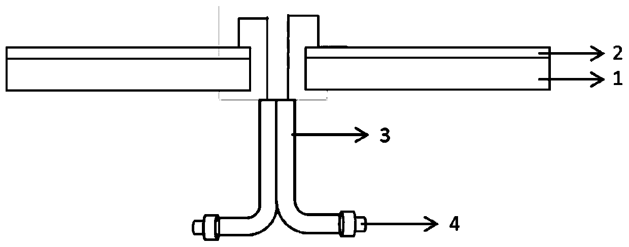
[0029] A cross-band frequency-changing antenna based on an intelligent origami structure of the present invention, its structural front section view is as follows figure 1 As shown, (component composition) includes 4D printing deformable origami substrate 1, antenna arm 2, coaxial feeder 3, SMA radio frequency coaxial connector 4 and RF signal transmitter;

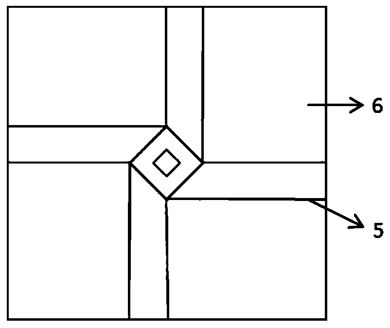
[0030]The 4D printing deformable origami substrate 1 is a self-locking square-twist folding structure printed by an Object 350 printer of Stratasys Company, with VeroWhite material as the panel 6 and TangoBlack material as the crease 5;

[0031] Among them, the plane size of the 4D printed deformable origami substrate 1 in the unfolded state is 195 x 195 mm 2 , with a thickness of 0.75mm, and its planar unfolded structure is as follows figure 2 As shown, the size of the central square of the 4D printed deformable origami base is 17.5 x 17.5 mm 2 , the center of the square has a 6 x 6mm opening 2 Square hole. After fol...

Embodiment 2

[0037] A cross-band frequency-changing antenna based on an intelligent origami structure of the present invention, its structural front section view is as follows figure 1 As shown, (component composition) includes 4D printing deformable origami substrate 1, antenna arm 2, coaxial feeder 3 and SMA RF coaxial connector 4;

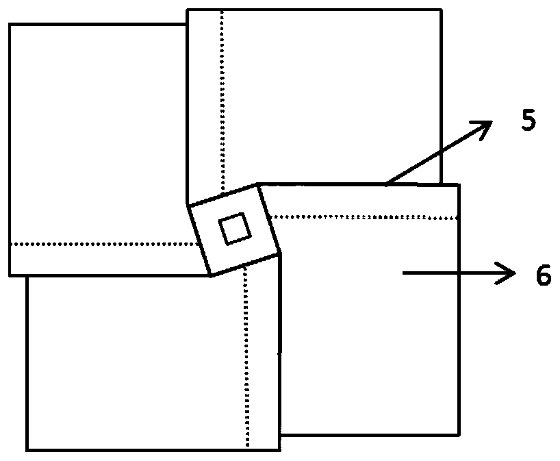
[0038] The 4D printing deformable origami substrate 1 is a self-locking square-twist folding structure printed by an Object 350 printer of Stratasys Company, with VeroWhite material as the panel 6 and TangoBlack material as the crease 5;

[0039] The plane size of the 4D printed deformable origami substrate in the unfolded state is 110 x 110 mm 2 , with a thickness of 0.5mm, the central square size of the 4D printed deformable origami substrate is 20 x 20 mm 2 , the center of the square has a 6 x 6mm opening 2 Square hole, its folded structure is as follows image 3 shown.

[0040] The printed 4D printed deformable origami base 1 is taken out, cleaned an...


PUM


Abstract

The present invention relates to a cross-band frequency-conversion antenna based on an intelligent paper folding structure, belonging to the field of frequency reconfigurable antennas. The antenna comprises a substrate, an antenna arms, a coaxial feeder, a radio frequency coaxial connector and a RF signal emitter; the substrate employs a self-locking square-twist folding structure; the middle portion of the substrate is provided with a cross-line hole, the two antenna arms are symmetrically glued and fixed at the upper side plate surface of the substrate, the initiating terminal of each antenna arm is extended outwards from the cross-line hole, each antenna arm is located the panel overlapping position for ducking in a folding state; the initiating terminals of the antenna arms are respectively connected with two output ports of the RF signal emitter through the coaxial feeder via the radio frequency coaxial connector, and output signal phase difference of two ends of the RF signal emitter is 180 degrees. The antenna can be subjected to self unfolding through heating to change working frequency, the influence of frequency modulation on performances of the antenna is little, the frequency tuning amplitude is large, and cross of different wave bands can be achieved.

Description

technical field [0001] The invention relates to a cross-band frequency conversion antenna based on an intelligent origami structure, and belongs to the field of frequency reconfigurable antennas. Background technique [0002] Frequency reconfigurable antennas are in urgent demand in satellite communications, global positioning, weather radar, drones and other fields. The essence of the frequency reconfigurable antenna is to change the working state of the antenna by changing the current distribution of the antenna radiator. This type of antenna can continuously or discretely adjust the working frequency within a certain frequency range, while maintaining the pattern, polarization and other characteristics. constant. With the development of wireless communication technology, frequency reconfigurable antennas can effectively reduce the cost and weight of wireless communication systems, realize miniaturization, and help solve electromagnetic compatibility problems between wire...

Claims


Application Information

Patent Timeline
Patent Type & Authority Patents(China)
IPC IPC(8): H01Q1/36H01Q1/50
CPCH01Q1/36H01Q1/50
Inventor 张亚静宋维力王莅辰陈明继方岱宁
Owner BEIJING INSTITUTE OF TECHNOLOGYGY
Why Eureka
Try Eureka