
Handheld power tool

a power tool and hand-held technology, applied in the direction of percussive tools, portable percussive tools, drilling machines and methods, etc., can solve the problems of increasing limiting the effective operation to a relatively limited torque range, and changing the frequency of striking, which is perceptible to the user, so as to reduce the total weight of the tangential striking mechanism

Active Publication Date: 2015-02-10
HILTI AG
View PDF27 Cites 3 Cited by
  • Summary
  • Abstract
  • Description
  • Claims
  • Application Information

AI Technical Summary

Benefits of technology

The solution provides a larger useful torque range with minimal increase in holding torque and constant striking frequency, allowing the motor rotational speed to remain largely unchanged, enhancing the tool's operational flexibility and ease of use.

Problems solved by technology

For the most part, tangential striking mechanisms within the scope of a spring-mass system are designed for the resonant operation of such a system, which usually restricts the effective operation to a relatively limited torque range.
A problematic aspect of the adaptation of a tangential striking mechanism—which can be basically structured as a spring-mass system like the friction clutch of European application EP 1 862 265 A2—is that any change in the spring force for the mass of the hammer in the tangential striking mechanism also leads to a change in the striking frequency, which is perceptible to the user.
Moreover, an increase in the spring force, for example, not only causes an increase in the striking force, but also causes the tangential striking mechanism to have a higher triggering torque, which means that the user has to apply a corresponding counter-torque onto the handle.
This has a detrimental effect on the handling of the handheld power tool.

Method used


Image

  • Handheld power tool
  • Handheld power tool
  • Handheld power tool

Examples


Embodiment Construction

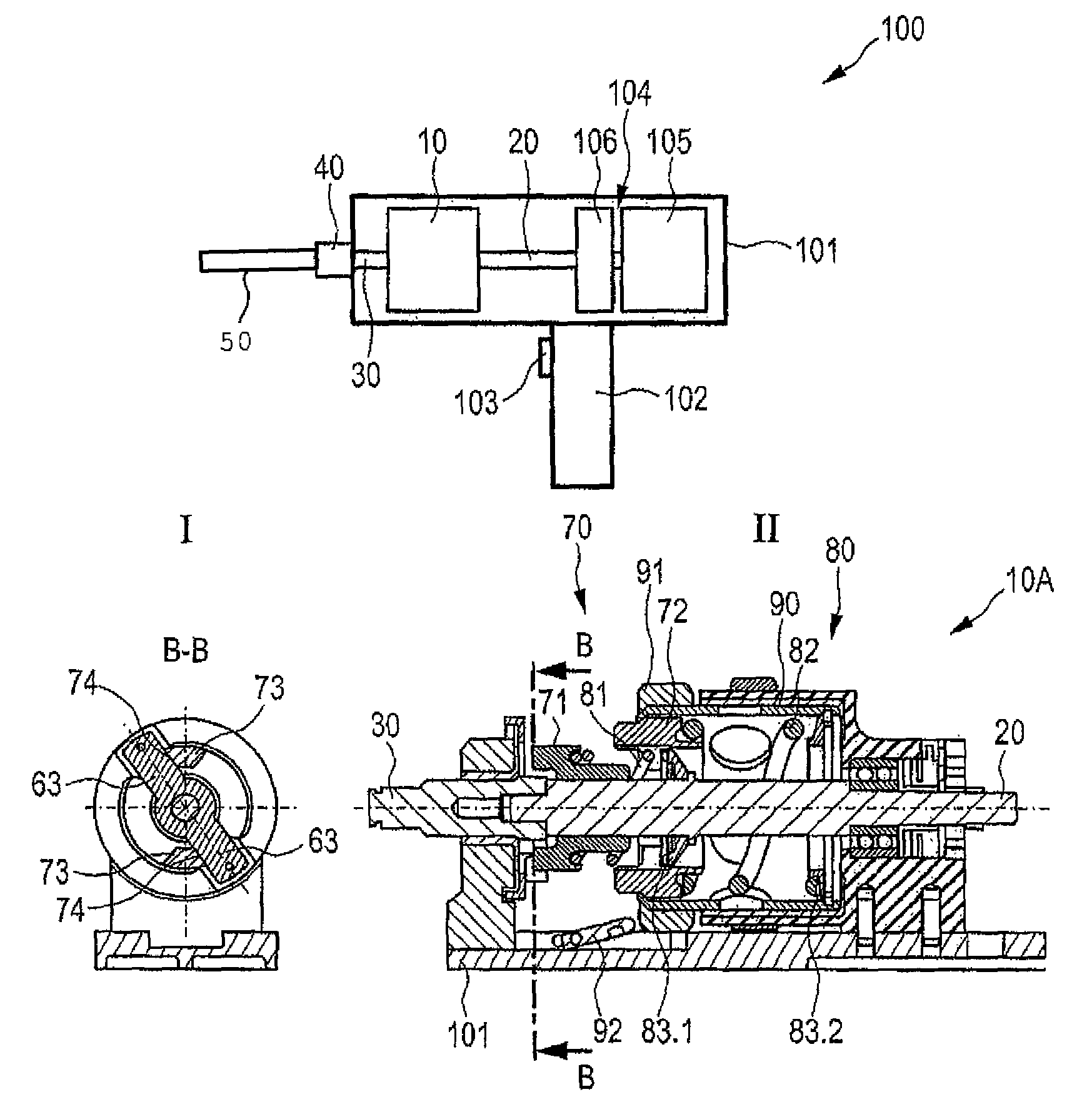
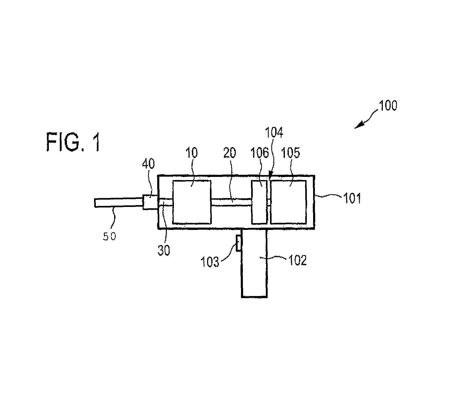
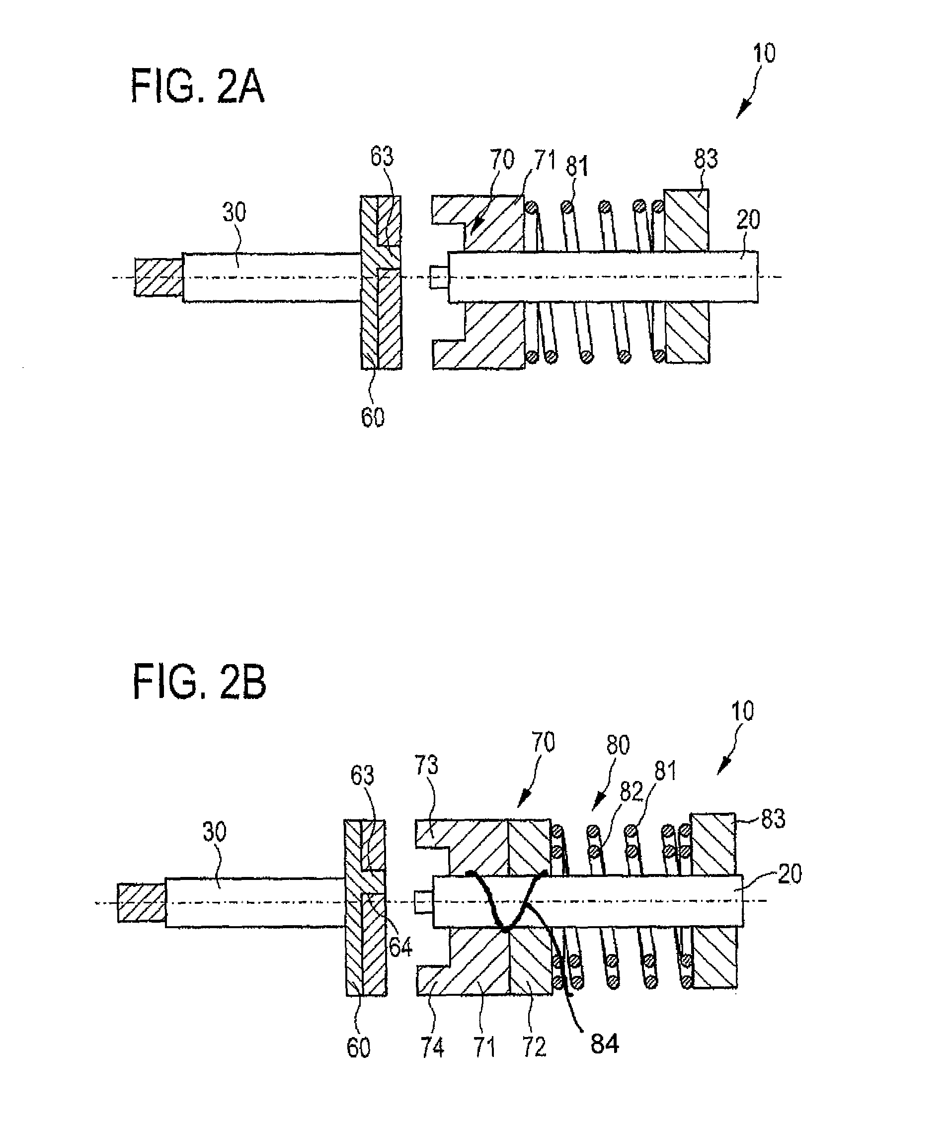
[0027]FIG. 1 shows a handheld power tool 100 which, for example, in the form of an impact screwdriver, can be held by a handle 102 formed on the housing 101, and whose drive 104 here can be activated with a trigger 103 in the form of a lever or a pushbutton. The drive 104 here is a motor 105 in the form of an electric motor that transfers a rotational movement indicated in FIG. 1 to a spindle 20 by means of a drive 106. By means of the tangential striking mechanism 10 described in greater detail in FIG. 2, the rotational movement 1 of the spindle 20 is converted into a partially tangentially striking movement of the drive shaft 30; this rotating and partially tangentially striking movement of the drive shaft 30 is transferred to a tool 50 (shown schematically) in a tool socket of the handheld power tool 100. The tool 50, for example, a screwdriver or the like, which is installed in the tool socket 40 on the same axis 2 as the spindle 20 and the drive shaft 30, is thus capable of tra...


PUM

PropertyMeasurementUnit
forceaaaaaaaaaa
massaaaaaaaaaa
stiffnessaaaaaaaaaa

Abstract

A handheld power tool, including a tool socket on a drive shaft for purposes of holding a tool, the drive shaft executing a rotating and partially tangentially striking movement using a tangential striking mechanism drivable by a drive. The tangential striking mechanism has an anvil associated with the drive shaft and a hammer associated with the drive, movable with respect to each other so as to strike each other axially when under the effect of the force of at least one first spring, and to strike each other tangentially when the anvil and the hammer are rotated. The hammer has a main mass, and an extra mass that is under the effect of a second spring couplable to the main mass.

Description

[0001]This claims the benefit of German Patent Application DE 10 2010 062 014.9, filed Nov. 26, 2010 and hereby incorporated by reference herein.[0002]The invention relates to a handheld power tool.BACKGROUND[0003]A mechanical tangential striking mechanism such as the one used in a handheld power tool of the above-mentioned type, for instance, in an impact screwdriver, allows the generation of relatively large torques on the tool socket, whereby only a relatively small counter-torque is needed. This is advantageous, for example, when screwed connections are being tightened or when screw anchors are being set into a very hard substrate. In particular, it is an option in such applications for the peak torque that can be provided by the tangential striking mechanism to be far higher than the continuous torque that can be provided by the drive of the handheld power tool. The lowest possible counter-torque is especially advantageous for users since they normally have to exert the counter...

Claims


Application Information

Patent Timeline
Patent Type & Authority Patents(United States)
IPC IPC(8): B25B21/02B25D16/00
CPCB25B21/02B25B21/026
Inventor HOOP, ALEXANDERBOENI, HANSPROFUNSER, DIETERBRUGGER, PETER
Owner HILTI AG
Learn More