
Calibration device and method for line scanning imaging

A line scanning and calibration technology, applied in the field of online scanning imaging, can solve problems such as inconsistent imaging states

Active Publication Date: 2021-05-11
BEIJING LUSTER LIGHTTECH
View PDF8 Cites 0 Cited by
  • Summary
  • Abstract
  • Description
  • Claims
  • Application Information

AI Technical Summary

Problems solved by technology

If the adjustment of each optical system is inconsistent, the imaging state will be inconsistent

Method used


Image

  • Calibration device and method for line scanning imaging
  • Calibration device and method for line scanning imaging
  • Calibration device and method for line scanning imaging

Examples


Embodiment Construction

[0055]In order to better understand the present application scheme, the technical solutions in the present application embodiment will be described in connection with the drawings in the present invention, and the technical solutions in the present application will be clear and completely described.

[0056]In some processes and claims in the present application and some of the above-described drawings, a plurality of operations occurring in a particular order, but it should be understood that these operations may not be followed in the order in this article. Execution or parallel execution, the serial number, such as 101, 102, etc., are simply used to distinguish various different operations, and the sequence number does not represent any execution order. Additionally, these processes can include more or less operations, and these operations can be performed in order or in parallel. It should be noted that "first", "second", etc. in this paper is to distinguish between different messa...


PUM


Abstract

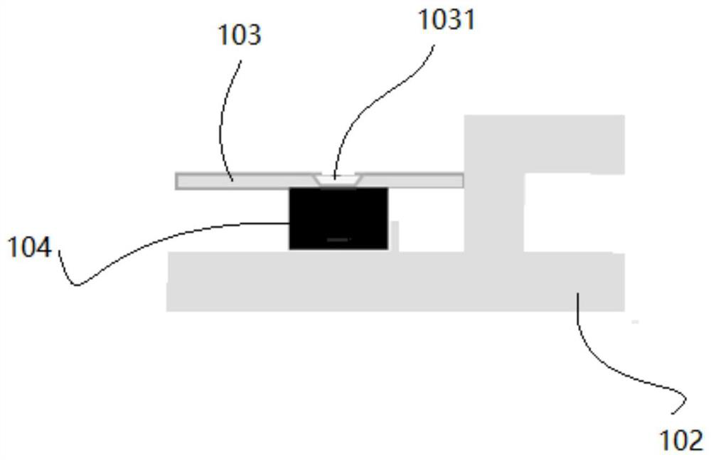
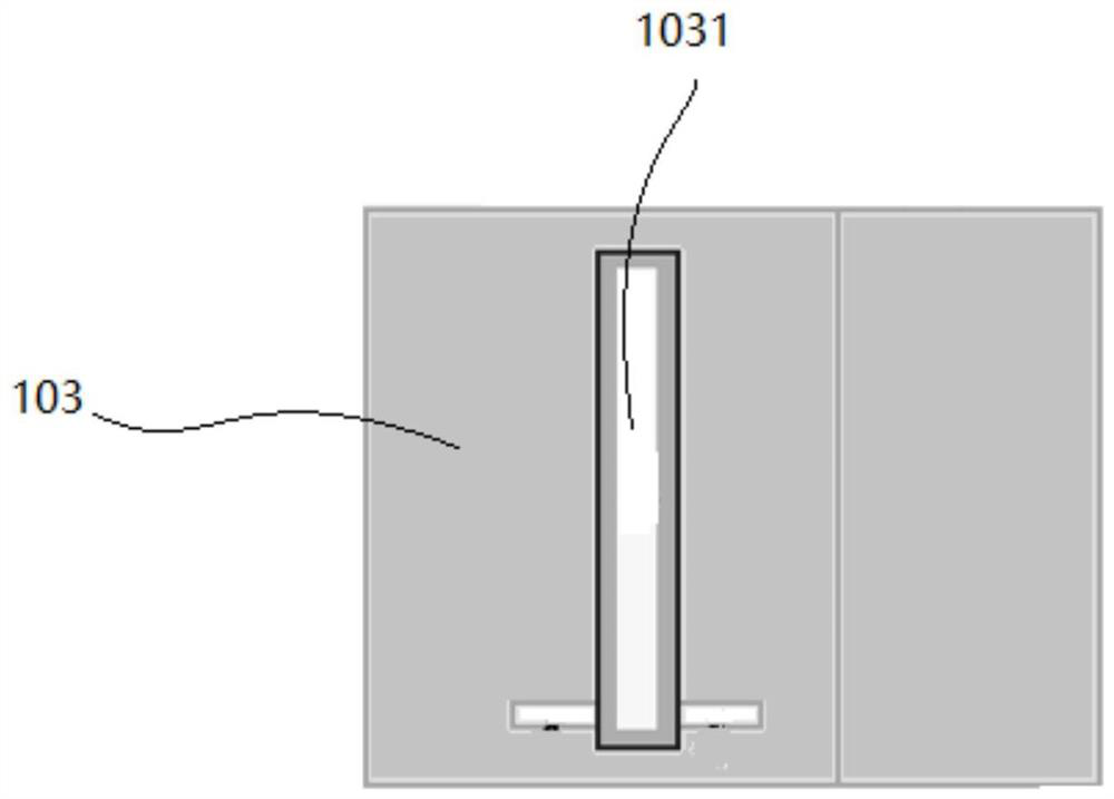
The invention discloses a calibration device for line scanning imaging. The device comprises a carrying platform, the carrying platform supports a fixed frame, the fixed frame supports a target placement platform which is consistent with the carrying platform in height and levelness, and the target placement platform is provided with a platform gap for light transmission; the fixed frame further supports a sensor arranged below the gap so that the sensor can display the position of a line light source in the X-axis direction when the line light source irradiates the sensor; the sensor is also integrated with a backlight source so that the backlight source is received by a camera for imaging through the platform gap; and the X-axis direction is the direction perpendicular to the platform gap in a horizontal plane. The calibration device can realize the debugging consistency of the line scanning imaging system on one hand, is high in debugging efficiency on the other hand, and can remarkably reduce the adjustment cost. In addition, the invention also discloses a calibration method for line scanning imaging.

Description

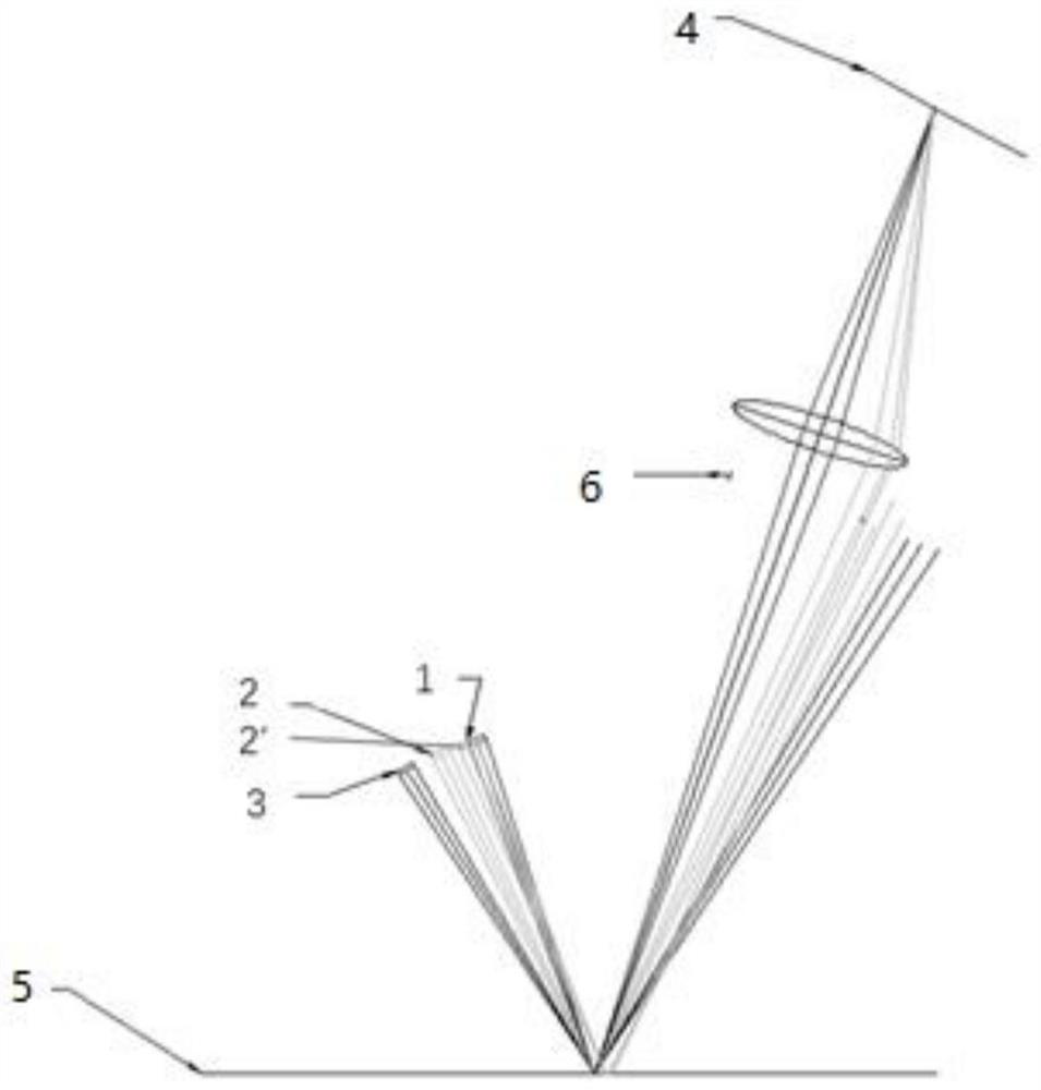
Technical field[0001]The present application relates to the field of line scan imaging, and in particular, to a scaler for wire scanning imaging. Further, the present application also relates to a scaling method for wire scanning imaging.Background technique[0002]Line light source mating line array cameras is a very common defect detecting device. Such asfigure 1 Distancefigure 1 For line light source imaging schematic. The light source is irradiated on a plane of the object to be inspected at a certain angle (which can be understood as an X-axis angle), and the light source is reflected into the camera target surface 4. It is assumed that the camera position is fixed, depending on the extent of the pore diameter stop according to the light source, it can be divided into three imaging states: the red light source 1 is reflected by the surface reflection of all fill the camera aperture, we call it tomography; green light source 2 and yellow light source 2 'The reflective portion of t...

Claims


Application Information

Patent Timeline
Patent Type & Authority Applications(China)
IPC IPC(8): G01N21/01G01N21/88
CPCG01N21/01G01N21/8851
Inventor 王丽艳邢志广赵严姚毅杨艺
Owner BEIJING LUSTER LIGHTTECH
Learn More