Balance car main control system, control system and balance car

A main control system, a technology of self-balancing vehicles, applied in general control systems, control/regulation systems, vehicle position/route/height control, etc., can solve problems affecting circuit stability, tedious installation, production obstacles, etc., and achieve stable communication. , to avoid maintenance and replacement, the effect of simplifying the production process

Pending Publication Date: 2021-05-11
ZHEJIANG AERLANG TECH CO LTD
0 Cites 0 Cited by

AI-Extracted Technical Summary

Problems solved by technology

[0003] The existing self-balancing vehicles have realized wireless control of music playback and data transmission functions, but these two functions are integrated on two independent PCB board modules, and the audio unit needs to be powered by the main board through t...

Method used

Embodiment 1 provides a kind of balancing vehicle main control system, aims at the bluetooth module and the power supply module of integrated control function, data transmission and bluetooth audio function through the main control system, guarantees bluetooth module communication stability, reduces external connection Wire and welding processes simplify the production process and reduce manufacturing costs. At the same time, each module of the main control system is powered by a power supply module to ensure normal operation, making the signal transmission more stable and realizing the control of one motor of the balance car.
The circuit of audio power amplifier module please refer to shown in Figure 4, and audio power amplifier module comprises audio frequency power amplifier chip, resistance R5, resistance R6, resistance R7, resistance R8, electric capacity C9, electric capacity C10, electric capacity C11 and plug-in cable P1. One end of the resistor R5 is connected to the audio power amplifier chip, the other end of the resistor R5 is connected to the power supply 5V, one end of the resistor R6 is connected to the audio power amplifier chip, the other end of the resistor R6 is connected to the power supply 5V, one end of the resistor R7 is connected to the audio power amplifier chip, and the other end of the resistor R7 is connected to the audio power amplifier chip. The other end is grounded, one end of the resistor R8 is connected to the audio power amplifier chip, the other end of the resistor R8 is connected to one end of the capacitor C9, the other end of the capacitor C9 is connected to the Bluetooth module, one end of the capacitor C11 is connected to the audio power amplifier chip, the other end of the capacitor C11 is grounded, and the other end of the capacitor C11 is connected to the ground. One end of C10 is connected to pin 6 of the audio power amplifier chip and grounded, one end o...

Abstract

The invention discloses a balance car main control system, and relates to the technical field of balance car control. The main control system comprises a Bluetooth module which detects a signal, processes the detected signal, sends a control signal, carries out the data communication with an external Bluetooth device, and outputs a Bluetooth audio signal; a motor driving module which is used for driving a motor to operate, a posture detection module which is used for acquiring the motion data of a balance car, an auxiliary control interface which is connected with an auxiliary control system, and a power supply module which is used for providing a working power supply for each circuit module of the main control system. The Bluetooth module is connected with the motor driving module and the posture detection module. The main control system ensures the communication stability of the Bluetooth module, simplifies the production process, and reduces the manufacturing cost. The invention further discloses a balance car control system and the balance car. The balance car control system adopts double systems to control the balance car, and the main control system and the auxiliary control system respectively control a motor of the balance car.

Application Domain

Technology Topic

Image

  • Balance car main control system, control system and balance car
  • Balance car main control system, control system and balance car
  • Balance car main control system, control system and balance car

Examples

  • Experimental program(6)

Example Embodiment

[0068]Example one
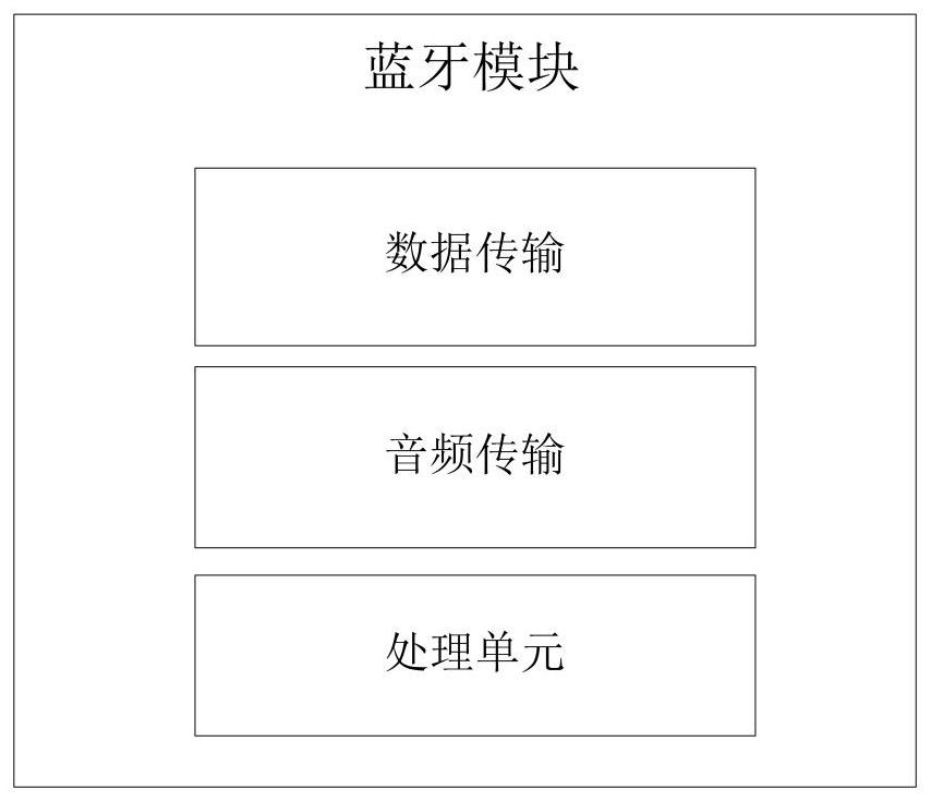
[0069]EXAMPLES One provides a balanced owner, intended to integrate control functions, data pass, and Bluetooth audio functions, to ensure the provision of Bluetooth modules, and reduce external connectivity and welding. Step, simplify production steps, reduce manufacturing costs, and all modules of the main control system use the power supply module to power, ensure normal operation, so that the stability of the signal transmission is stronger, and the control of one motor of the balance vehicle is realized.
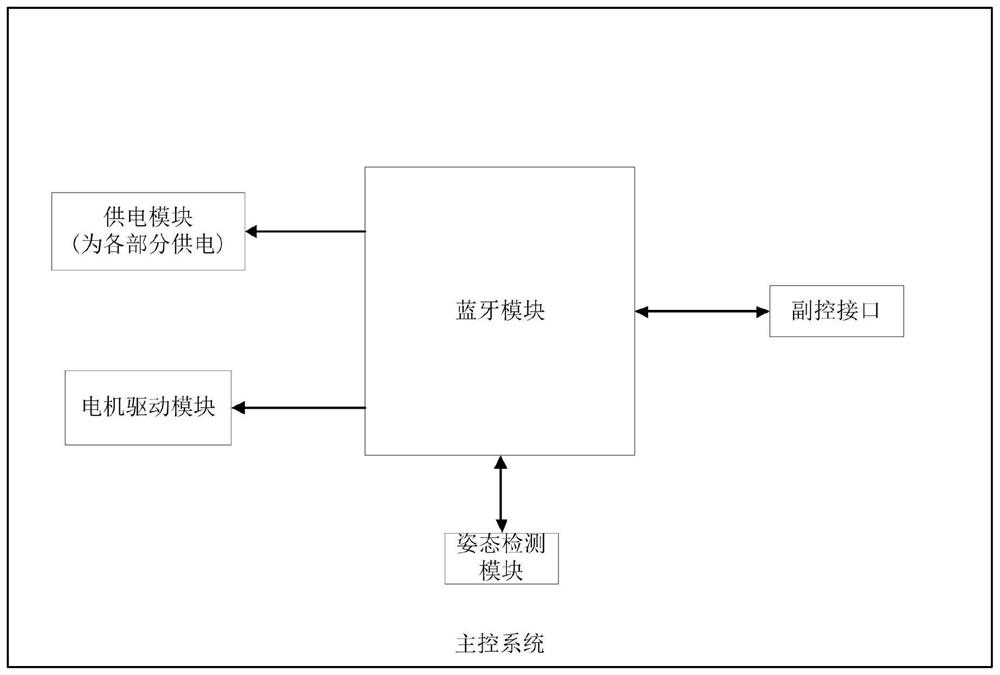
[0070]Please refer tofigure 1 As shown, a balanced owner control system, including Bluetooth modules, motor drive modules, posture detection modules, deposition interfaces, and power modules. The Bluetooth module is used to detect the signal, the detection signal processing, and the transmission control signal, the Bluetooth module can use a variety of embedded microcontrollers for various integrated Bluetooth transmission functions, detect the detection signals input by each circuit module, and outputs each circuit module in the main control system Control signals implement various control functions. For the Bluetooth module, please refer tofigure 2 As shown, the Bluetooth module includes a Bluetooth chip, a resistor R21, and a capacitor C15. Bluetooth chip pin 1, pin 9, pin 36, pin 48 connection power supply VD, Bluetooth chip pin 8, pin 23, pin 35, pin 44, pin 47 ground, resistor R21 Between the Pin 7 of the Bluetooth chip and the power supply VD, the capacitor C15 is connected between the pin 7 and the ground of the master chip. The pin 24 of the Bluetooth chip is connected to the Bluetooth antenna E, passed by the capacitor C22 and the Bluetooth antenna E of the capacitor C22, and the Pin U0-3, pin U0-4, pin U0-3 of the Bluetooth chip at the connection point of the capacitor C22 and the Bluetooth Antenna E. 10, pin U0-11, Pin U0-12, pin U0-13, pin U0-14, pin U0-15, pin U0-16, pin U0-17, pin U0-18, Pin U0-20, pin U0-21, pin U0-22, pin U0-25, pin U0-26, pin U0-27, pin U0-28, pin U0-29, pin U0-30, pin U0-31, pin U0-32, pin U0-34, pin U0-37, pin U0-38, pin U0-39, pin U0-40, pin U0- 41, pin U0-42, pin U0-43, pin U0-46, etc. Other pins for detecting the transmission of signals or control signals. Other reserved pins can connect other circuit modules to achieve corresponding control functions.
[0071]The Bluetooth module is used to receive control signals, communicate with external Bluetooth devices and output Bluetooth audio signals. The external Bluetooth device can be an external device with a Bluetooth transmission function, such as a mobile phone, a Bluetooth bracelet, a Bluetooth helmet, a Bluetooth control switch, and the like, and an external Bluetooth device includes, but is not limited to, the above components can improve the use of the balanced vehicle. The Bluetooth module connects the audio power amplifier module, and the audio power amplifier module enlarges the Bluetooth audio signal.
[0072]The Bluetooth module can also be replaced with control chips with other wireless transmission functions such as WiFi.
[0073]Bluetooth module function block diagram, please refer toimage 3 As shown, the Bluetooth module includes a data transmission unit for receiving data such as a control signal such as an external Bluetooth, an audio transmission unit, an audio signal for receiving an external Bluetooth device, and a data processing unit, calculating various input data and output control signals. Give other modules. The above unit may be a unit divided by hardware or a unit divided by a function.
[0074]Circle of the audio amplifier module, please refer toFigure 4 As shown, the audio power amplifier module includes an audio power transfusion chip, a resistor R5, a resistor R6, a resistor R7, a resistor R8, a capacitor C9, a capacitor C10, a capacitor C11, and a plug-in cable P1. One end of the resistor R5 is connected to the audio power amplifier chip, the other end of the resistor R5 is connected to the power supply power source 5V, and one end of the resistor R6 connects the audio power amplifier chip, and the other end of the resistor R6 is connected to the power supply power supply 5V, and one end of the resistor R7 connects the audio power amplifier chip, the resistance R7 On the other end, one end of the resistor R8 is connected to the audio power amplifier chip, the other end of the resistor R8 connects the capacitor C9, and the other end of the capacitor C9 is connected to the Bluetooth module, and one end of the capacitor C11 connects the audio power amplifier chip, the other end of the capacitor C11, and the capacitor. One end of C10 connects the pin 6 of the audio power, and grounds, one end of the capacitor C10 connected to the pins 7 of the audio power amplifier chip and connects the power supply 5V, and the web P1 is connected to the audio power amplifier chip. The silent switch signal output by the Bluetooth module inputs an audio amplifier chip by resistor R1, and the Bluetooth module outputs analog audio sequentially passes the capacitor C9, the resistor R8 inputs an audio power amplifier chip. The audio amplifier chip is connected to the audio device by connecting the cable P1. The audio device can be various types of speakers, microphones, etc. have audio output devices such as headphones, headset microphones, headphones, headphones, and audio equipment. Including but not limited to the above components, improve the performance of the balanced vehicle.
[0075]Motor drive module, for driving the motor, and the motor drive module connects the Bluetooth module. The motor drive module includes a first semi-bridge gate driving circuit, a second half bridge gate driving circuit, and a third half bridge gate driving circuit, and three half bridge gate drive circuit configurations are the same.
[0076]Circuit for motor drive module, please refer toFigure 5 As shown, the first half bridge gate driving circuit includes a half bridge gate driving circuit chip U6, a diode D1, a capacitor C105, a resistor R31, a resistor R33, an NMOS tube QB2, a resistor R32, a resistor R34, NMOS tube QB1, resistance R11c, and Interface TA5, NMOS Tube QB2 and NMOS Tube QB1 form a set of NMOS pairs. The half-bridge gate driving circuit chip U6 pin 2, the pin 3 connects the Bluetooth module pin U0-31, U0-28, the half-bridge gate driving circuit chip U6 pin 4 ground, the anode connection of the diode D1 The pin 1 of the bridge gate drive circuit chip U6, and the pin 1 of the half bridge gate driving circuit chip U6 is connected to the power source Vb, the cathode connection of the diode D1 is connected to the pin 8 of the half-bridge gate driving circuit chip U6, the capacitor C105 connection Between the pin 8 of the half bridge gate driving circuit chip U6, the electrical resistance R31 is connected to the pin 7 and NMOS tube QB2 of the half bridge gate driving circuit chip U6. Between the gate, the resistor R33 is connected between the gate of the NMOS tube QB2 and the pin 6 of the half bridge gate driving circuit chip U6, the drain connection of the NMOS tube QB2 is connected to the source VA, the source and NMOS tube of the NMOS tube QB2. The drain connection of QB1, and the source of the NMOS tube QB2, the drain of the NMOS tube QB1 is connected to the interface TA5, and the resistor R32 is connected between the leading foot 5 of the half bridge gate driving circuit chip U6 and the gate of the NMOS tube QB1. The resistor R34 is connected between the gate and the source of the NMOS tube QB1, and the resistor R11c is connected between the source and the drain of the NMOS tube QB1, and the source output current of the NMOS tube QB2 is connected to the interface TA5 external motor.
[0077]The output current of the first half bridge gate driving circuit NMOS tube QB2 is passed through the motor to the second half bridge gate driving circuit NMOS tube QB3; the second half bridge gate driving circuit NMOS tube QB4 output current, after the motor to the third The half bridge gate driving circuit NMOS tube QB5; the output current of the third half bridge gate driving circuit NMOS tube QB6 is passed through the motor to the first half bridge gate driving circuit NMOS tube QB1.
[0078]The pins 2 and pins 3 of the three half-bridge gate drive circuit chips are connected to the Bluetooth module, and the motor rotation signal of the Bluetooth module is received. According to the motor rotation signal, the battery voltage is converted to the corresponding driving motor to operate the high voltage signal, output it The connected NMOS is closed and disconnected by controlling the three sets of NMOS pairs, and the drive motor is inversely rotating.
[0079]The gesture detection module is used to obtain motion data of a balanced car, which connects the Bluetooth module. The gesture detection module includes a gyroscope, the gyroscope can use a motion processing chip for detecting the motion data information of balancing the vehicle body and the like of the angular velocity and acceleration of the vehicle body, and uses the digital motion processor, I2C interface, and test. The analog is converted to a digital, obtains an accurate inclination value, conveys to the Bluetooth module.
[0080]Circuit for posture detection module, please refer toFigure 6 As shown, the posture detection module includes two motion processing chips. The motion treatment chip U1 pin 24, pin 23 connects the resistor R17, the port 2 of the resistor R18, the port 1 of the resistor R17, and the resistor R18, respectively, and the Bluetooth module pin U0-43, U0-42, the motion processing chip U3 pin 2, the pin 3 connects the resistor R18, the port 2 of the resistor R17, and the resistor R15 is connected between the resistor R17 and the power supply VD, and the resistor R16 is connected between the resistor R18 and the power supply VD; the pins 22 of the motion processing chip U1, Head 13, pin 8 Connect the power supply VD, the pin 20 of the motion processing chip U1, the pin 18, the pin 9, the pin 11 ground, the capacitor C7 is connected to the pins 10 and the ground between the motion processing chip U1; Treatment chip U3 pin 1, pin 5, pin 16 connection power supply VD, motion processing chip U3 pin 4, pin 8, pin 9, pin 10, pin 11, pin 12, pin 13, pin 15 ground, capacitor C25 is connected to between the pins 14 and the ground of the motion processing chip U3. In actual use, according to cost or stock conditions, it is used in two chips.
[0081]Balance the authorized interface of the owner control system for connecting to the deputy control system, the deposition interface connects the Bluetooth module, implements communication with the deputy control system.
[0082]The power supply module is used to provide a working power supply to each circuit module in the main control system. Make sure that each circuit module works normally, making the signal transmission stability in the main control system.

Example Embodiment

[0083]Example 2
[0084]Embodiment 2 is an improvement performed on the basis of the embodiment, in order to meet the different power supply requirements of the respective circuit modules of the master system, the power supply module provides high voltage of the battery power source through the first power supply unit, the second power supply unit, and the third power supply unit. Down to different supply voltages, the first power supply unit, the second power supply unit, and the third power unit are sequentially connected. The first power supply unit reduced the power supply voltage Va as a voltage Vb, and the second power supply unit degraded the voltage Vb to a voltage Vc, and the third power supply unit degraded the voltage Vc to a voltage VD. The voltage Vd output from the third power supply unit is powered by the Bluetooth module, and the voltage Vc output from the second power unit is powered by the audio power amplifier module. The second power supply unit includes a low pressure difference linear regulator step-down chip U1, and the third power supply unit includes a low pressure difference linear regulator buck chip U2.
[0085]The power supply module also includes interface BLE1, interface Ble1 is reserved, powered by the peripheral device. Peripherals include batteries, motors, light strips, lighting, power-on switches, etc., peripherals include, but are not limited to, the above components, can improve the use of balancing vehicles.
[0086]The first power supply unit includes enable circuitry, a buck circuit, and a filter circuit, the enable circuit connected to the step-down circuit, and the step-down circuit connects the filter circuit. The enable circuit is configured to receive the control signal of the Bluetooth module, and control power is controlled according to the control signal; the step-down circuit is used to convert the high voltage provided by the battery to a low pressure; the filter circuit is used for filtering Deficit noise signal. The filtering unit is a plurality of capacitance values ​​of different capacitance values, and the specific capacitance value is determined according to the actual circuitry. Circuit for power supply module, please refer toFigure 7 Indicated.
[0087]The enable unit receives the power-on signal of the balance vehicle switch button, and activates the buck unit for voltage conversion. The enable unit includes a capacitance C24, a resistor R86, a resistor R84, a diode D8, a resistor R85, a resistor R81, a resistor R80, a transparent Q13, a resistor R79, an interface J1; wherein the first end of the resistor R86 is connected to the Bluetooth module, the resistance R86 The anode of the second-end connection diode D8, the first end of the capacitor C24 connects the Bluetooth module, the second end of the capacitor C24, the first end of the resistor R84 connects the anode of the diode D8, the second end of the resistor R84, the anode of the diode D8 A port of the connection interface J1, one end of the interface J1 connects the resistor R79, grounding the other end of the resistor R79, the first end of the resistor R85 connects the diode D8 cathode, the second end of the resistor R85 connects the base of the triode Q13, The first end of the resistor R80 is connected to the Bluetooth module, and the second end of the resistor R80 is connected to the triode Q13 base, and the first end of the resistor R81 is connected to the triode Q13 base, and the second end of the resistor R81 is connected to the triode Q13 emitter, and the triode The emitter of Q13 is grounded.
[0088]The enable unit further includes a triode Q10, a resistor R77, a resistor R78, a resistor R92, a resistor R93, a resistor R94, a resistor R82; wherein the first end of the resistor R77 connects the secondary electrode, the second end of the resistor R77, Q10 group. The first end of the electrode, the first end of the resistor R78 is connected to the second end of the resistor R78 connects the triode Q10 emitter, the emitter of the triode Q10 is connected to the power source Va, the first end of the resistor R92 connects the collector, resistance of the triode Q10. The second end of the R92 connects the first end of the resistor R93, the second end of the resistor R93 connects the Bluetooth module, and the first end of the resistor R94 connects the Bluetooth module, the second end of the resistor R94; the resistor R82 is connected to the triode Q10 The collector, the resistor R82 second end is connected to the step-down circuit.
[0089]Interface J1 Connect the switch button of the balance car, when the balance vehicle is closed, press the button, balance the electric power supply, the power supply VA passes through the dielectric tube D8, the triode Q13, the triode Q13, the triode Q10, and the power supply module pair various circuit modules Power supply, the Bluetooth module detects the battery voltage Va through the port U0-14, and the Bluetooth module detects the power signal by the port U0-15, the Bluetooth module transmits the power supply signal via the port U0-20, holding the power supply module, holding the triode Q13, and the power supply module Keep the power supply, the button is pressed and the rebound does not affect the power supply module to power the module of the main control system; the power failure process is consistent with the power-on process.
[0090]The step-down circuit includes: a step-down chip U12, a resistor R83, a resistor R46, a resistor R90, a capacitor C91, a diode D20, an inductance L2, a capacitor C89, a resistor R88, and a resistor R87; the first end of the resistor R83 is connected to a buck chip U12. The pin 1, the second end of the resistor R83 connects the pin 2 of the step-down chip U12, and the first end of the resistor R46 is connected to the pin 3, the first end of the resistor R46 connects the step-down chip U12. The pin 4, and the pin 4 of the step-down chip U12 is grounded, the first end of the resistor R90 connects the pin 7 of the step-down chip U12, the second end of the resistor R90 connects the first end of the capacitor C91, the capacitor C91 The second end is connected to the pin 8 of the step-down chip U12, the cathode of the diode D20 is connected to the pin 8 of the step-down chip U12, and the anode of the diode D20 is grounded, the first end of the capacitor C89, the first end and the step-down chip of the resistor R88. The pin 4 of the U12 is connected, the second end of the capacitor C89, the second end of the resistor R88 and the pin 5 of the step-down chip U12 are connected, and the first end of the resistor R87 connects the built-in chip U12 pin 4, the resistor R87 The first end is grounded, the first end of the inductor L2 is connected to the pin 5 of the step-down chip U12, and the second end of the inductance L2 is connected to the pin 8 of the buck chip U12; the inductance L2 is used to output the high frequency output by the buck chip U12. The cycle signal is converted to a DC signal.

Example Embodiment

[0091]Example three
[0092]Embodiment 3 is an improvement performed on the basis of the first or embodiments, and the balanced owner includes a brake detection module and a current detecting module. The brake detection module is configured to detect the motor drive module current, the brake detection module to connect the motor drive module and the Bluetooth module. The current detecting module is configured to detect the motor operating current, the current detecting circuit to connect the motor drive module and the Bluetooth module. The power supply module provides the required operating voltage for the brake detection module and the current detection module.
[0093]Circle of the brake detection module, please refer toFigure 8 As shown, the brake detection module includes a capacitor C29, a resistor R110, a resistor R109, a triode Q1, and a resistor R108; a first end of the capacitor C29 connected to the Bluetooth module, the second end of the capacitor C29, and the first end of the resistor R110 connects the Bluetooth module. The second end of the resistor R110 connects the collector of the triode Q1, the first end of the resistor R109 connected to the power source Vd, the second end of the resistor R109 connects the collector of the triode Q1, the emitter of the triode Q1, and the first end of the resistor R108. The base of the triode Q1 is connected to the second end of the resistor R108 connected to the motor drive module. When the current of the motor drive module is too large, the brake detection module receives the signal of the Bluetooth module through the port U0-25, and the triode Q1 is turned on, the hardware trigger motor drive module outputs the power failure or system power failure.
[0094]The current detecting module and the motor drive module are connected, and the port 1 connected to the resistor R0N0, the port 2 of the resistor R0N0 is grounded, and the resistor R0N0 is the millis sampling resistor R. The current detecting module detects the power-on differential pressure of the milligara sampling resistor R0N0, and the detection signal is enlarged into the Bluetooth module by an operational amplifier. Please refer toFigure 9 As shown, the current detecting module includes an operation amplifier U5a, a resistor R102, a diode D14, a resistor R100, a resistor R103, a resistor R96, a resistor R97, an operational amplifier U5B, a resistor R104, a diode D15, a resistor R98, and a resistor R99. .
[0095]The pin 1 of the operation amplifier U5A is connected to the Bluetooth module pin U0-18, and the resistor R102 is connected to the pin 2 of the operational amplifier U5A, between the Bluetooth module pin U0-18, the cathode connection operation of the diode D14 is connected to the pin 2 The anode connection operation of the diode D14 is connected to the pin 3, and the resistor R100 is connected to the pin 3 and ground of the operational amplifier U5a, and the resistor R103 is connected to the cathode of the diode D14 and the output of the motor drive module, the resistor R96 One end is connected to the pin 3 of the operational amplifier U5a, and the other end of the resistor R96 connects the resistor R97, and the other end of the resistor R97 is connected to the motor drive circuit.
[0096]Pin 1 of the operational amplifier U5B connected to the Bluetooth module pin U0-17, the resistor R104 is connected to the pin 6 of the operational amplifier U5B, between the Bluetooth module pin U0-17, the diode D15 cathode connection operation amplifier U5B pin 6 The pins 5 of the diode D15 are connected to the operation amplifier U5B, and the resistor R101 is connected between the pin 5 and the ground of the operation amplifier U5B, and the resistor R105 is connected to the cathode of the diode D15 and the output terminal of the motor drive module, the resistor R98 One end is connected to the pin 5 of the operation amplifier U5B, and the other end of the resistor R98 connects the resistor R99, and the other end of the resistor R99 is connected to the motor drive circuit.
[0097]The current detecting module also includes a resistor R107, a capacitor C2, and a resistor R106, and the resistor R107 is connected between the Bluetooth module pin U0-16 and the power supply VD, and the capacitor C2 is connected to the Bluetooth module pin U0-16 and the ground, the resistor R106 connection Between the Bluetooth module pin U0-16 and the motor drive module. The circuit detects the total current of the motor drive module.
[0098]The current detecting module detects the U-phase current and X phase current of the motor drive module, and the total current of the motor drive module. The current detecting module inputs the detection signal of the U-phase current of the U-phase current, the detection signal of the X-phase current, and the overcurrent detection signal of the total current of the total current, respectively, respectively, respectively. The Bluetooth module obtains an overcurrent detection signal through the port U0-16. When the total current is too large, the Bluetooth module performs a dramatic action for the motor drive module, the Bluetooth module adjusts the PWM duty cycle of the motor drive module.

PUM

no PUM

Description & Claims & Application Information

We can also present the details of the Description, Claims and Application information to help users get a comprehensive understanding of the technical details of the patent, such as background art, summary of invention, brief description of drawings, description of embodiments, and other original content. On the other hand, users can also determine the specific scope of protection of the technology through the list of claims; as well as understand the changes in the life cycle of the technology with the presentation of the patent timeline. Login to view more.

Similar technology patents

Robot remote communication system

InactiveCN110568785AEasy to control the robot remotelyStable communicationProgramme controlComputer controlGsm moduleWireless
Owner:安徽玄离智能科技股份有限公司

Classification and recommendation of technical efficacy words

  • Stable communication
  • Simplify the production process

Hot-rolled pickled plate and production method thereof

Owner:ZHANGJIAGANG YANGTZE RIVER COLD ROLLED PLATE CO LTD

Production method of dipotassium phosphate

InactiveCN104003362ASimplify the production processReduce energy and water consumptionPhosphorus compoundsPotassium hydroxideHeavy metals
Owner:GUIYANG KAILIN FERTILIZER CO LTD +1
Why Eureka
Try Eureka