Electrical engineering cable protection device

A protection device and electrical engineering technology, applied in electrical components and other directions, can solve the problems of cable damage, complicated disassembly and assembly, inconvenient transportation, etc., and achieve the effect of convenient disassembly and assembly, easy to use, and good protection.

Inactive Publication Date: 2021-05-11
SHANDONG HUAYU UNIV OF TECH
View PDF10 Cites 2 Cited by
  • Summary
  • Abstract
  • Description
  • Claims
  • Application Information

AI Technical Summary

Problems solved by technology

[0003] In the construction of electrical engineering, it is often necessary to set up a large number of cables and set up some supporting devices for the cables. However, the overall structure of the existing cable supporting devices is fixed, which makes transportation inconvenient, and the shockproof protection of the cables is not good. , easy to cause damage to the cable
At the same time, only the electrical engineering cables of the inner layer can be protected during transportation, while the damaged cables of the outer layer cannot be protected
[0004] In addition, the existing electrical engineering cable protection devices on the market generally use cylindrical sleeves to protect the cables, the cables are in direct contact with each other, and the protection devices are directly exposed to the outside world, and most of the existing cable protection devices do not It is possible to protect multiple cables separately, and it is inconvenient to adjust the protection device, resulting in a large amount of heat generated by the cable, which is easy to cause the cable to be burned and easily corroded, which reduces the service life of the protection device. Complicated

Method used


Image

  • Electrical engineering cable protection device
  • Electrical engineering cable protection device
  • Electrical engineering cable protection device

Examples


Embodiment

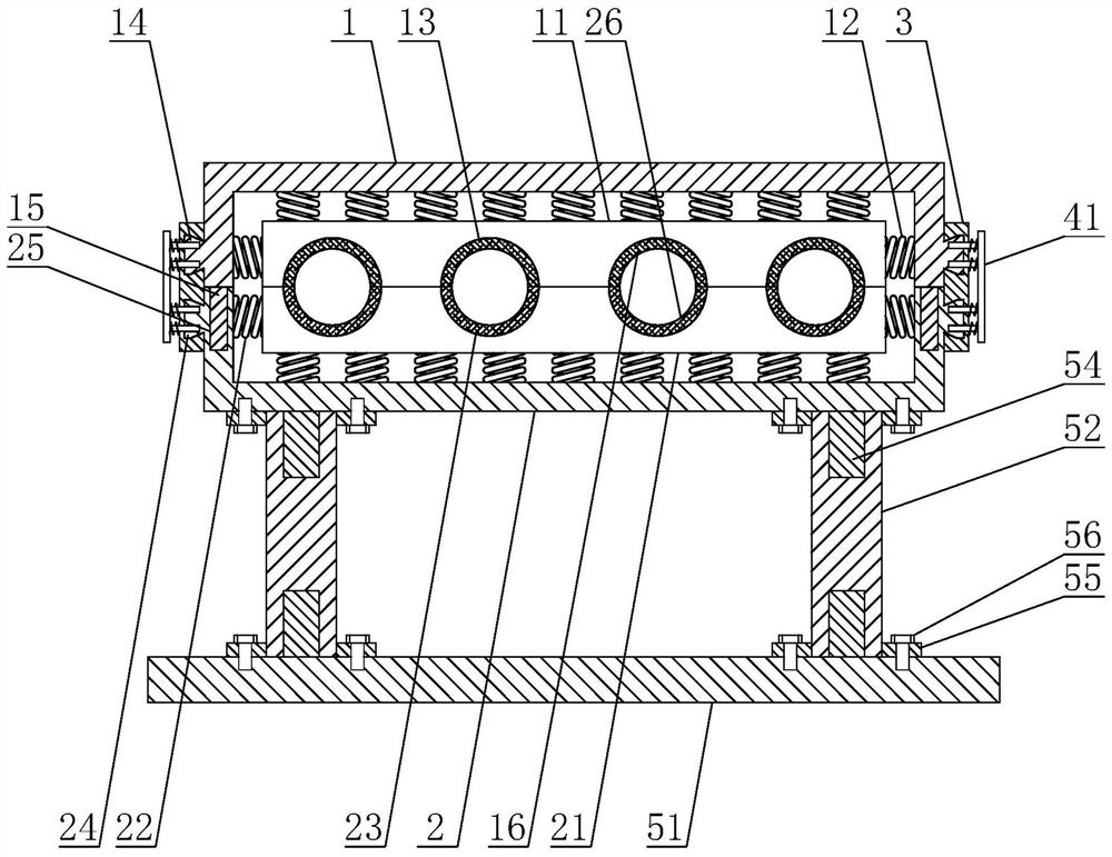
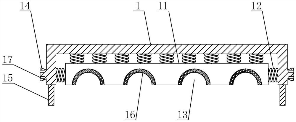
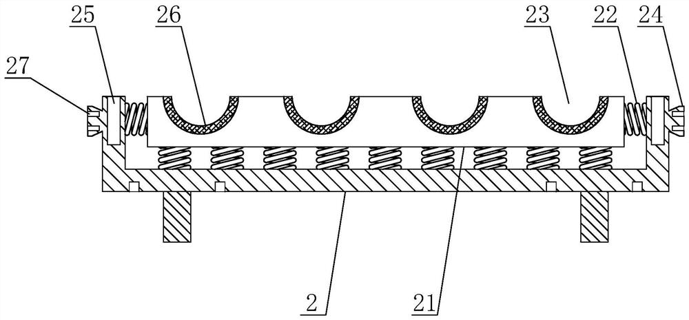
[0040] Example: as attached Figure 1-6 As shown, the present invention is an electrical engineering cable protection device, comprising:

[0041] Upper U-shaped frame 1, the upper U-shaped frame 1 can be formed by bending plates, the opening of the upper U-shaped frame 1 faces downward, and an upper clamping block 11 is arranged inside the upper U-shaped frame 1, and the upper U-shaped frame 1 is provided with an upper clamping block 11. There is a gap between the outer wall of the clamping block 11 and the inner wall of the upper U-shaped frame 1, the top of the upper clamping block 11 and the left and right ends of the upper clamping block 11 are all provided with an upper spring 12, and the upper spring 12 The quantity is determined according to the size of the upper clamping block 11. One end of the upper spring 12 is fixedly connected to the outer wall of the upper clamping block 11, and the other end is connected to the fixed inner wall of the upper U-shaped frame 1. Th...


PUM


Abstract

The invention discloses an electrical engineering cable protection device, and mainly relates to the technical field of electrical engineering. The device comprises an upper U-shaped frame, an upper clamping block being arranged in the upper U-shaped frame, upper springs being arranged at the top of the upper clamping block and the left end and the right end of the upper clamping block, a plurality of upper semicircular clamping grooves being formed in the bottom of the upper clamping block, and upper clamping blocks being arranged at the left end and the right end of the upper U-shaped frame; a lower clamping block, arranged in the lower U-shaped frame, lower springs being arranged at the bottom of the lower clamping block and the left end and the right end of the lower clamping block, a plurality of lower semicircular clamping grooves being formed in the top of the lower clamping block, and lower clamping blocks being arranged at the left end and the right end of the lower U-shaped frame; and a connecting block, an upper clamping groove being formed in the upper portion of the side wall of the connecting block, and a lower clamping groove being formed in the lower portion of the side wall of the connecting block. According to the invention, the cable can be effectively buffered and protected, can be quickly disassembled and assembled, can be divided into a plurality of components, and is convenient to transport, carry and use.

Description

technical field [0001] The invention relates to the technical field of electrical engineering, in particular to an electrical engineering cable protection device. Background technique [0002] Electrical engineering is the core and key discipline in the field of modern science and technology. For example, it is the great progress of electronic technology that promotes the arrival of the information age based on computer networks and will change the way of human life and work. Traditional electrical Engineering is defined as the sum of related disciplines used to create electrical and electronic systems. This definition is already very broad, but with the rapid development of science and technology, the concept of electrical engineering in the 21st century has gone far beyond the scope of the above definition. A Stanford University professor pointed out that today's electrical engineering covers almost all engineering activities related to electronics and photons. [0003] I...

Claims


Application Information

Patent Timeline
Patent Type & Authority Applications(China)
IPC IPC(8): H02G3/34
CPCH02G3/34
Inventor 陈现浩李浩楠郭运壮苏秋月王俊彬
Owner SHANDONG HUAYU UNIV OF TECH
Why Eureka
Try Eureka