Check patentability & draft patents in minutes with Patsnap Eureka AI!

Lock panel structure and intelligent lock

A panel and lock technology, applied in the field of locks, can solve problems such as breakage, time-consuming rework, and high overall cost, and achieve the effects of protecting reliable connections, reducing costs, and improving assembly quality and assembly efficiency

Pending Publication Date: 2021-05-14
广东好太太智能家居有限公司
View PDF0 Cites 0 Cited by
  • Summary
  • Abstract
  • Description
  • Claims
  • Application Information

AI Technical Summary

Benefits of technology

This patented technology allows for better protection against damage caused during installation without having to pull up any parts like an antenna wire harnesses attached to each door latch mechanism. It also improves assembly accuracy and reduces cost compared with traditional methods such as attaching cables between components beforehand.

Problems solved by technology

This patented technical problem addressed in this patents relates to improving the design of current smart locks that have a single handgrips instead of two hands or require complex wiring connections between components such as buttons.

Method used


Image

  • Lock panel structure and intelligent lock
  • Lock panel structure and intelligent lock
  • Lock panel structure and intelligent lock

Examples


Embodiment Construction

[0039] Below, the present invention will be further described in conjunction with the accompanying drawings and specific implementation methods. It should be noted that, under the premise of not conflicting, the various embodiments described below or the technical features can be combined arbitrarily to form new embodiments. .

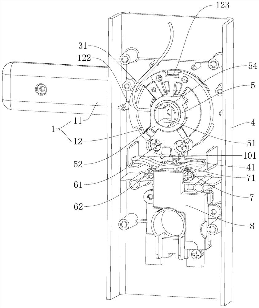
[0040] see Figure 1-Figure 7, shows a lock panel structure in a preferred embodiment of the present invention, including a handle assembly 1, a mounting seat 2, a fingerprint module 3 and a panel 4; the handle assembly 1 includes a handle 11 located outside the panel 4 And the handle joint 12 located on the inner side of the panel 4, the handle joint 12 can rotate axially under the drive of the handle 11; the mounting seat 2 is located in the handle 11, and the mounting seat 2 is provided with a mounting part 21 and a connecting part 22; The fingerprint module 3 is installed on the installation part 21, the fingerprint module 3 is provided with a fin...


PUM


Abstract

The invention discloses a lock panel structure and an intelligent lock. The lock panel structure comprises a handle assembly, a mounting base, a fingerprint module and a panel; the handle assembly comprises a handle arranged on the outer side of the panel and a handle connector arranged on the inner side of the panel, and the handle connector can axially rotate along with the handle; the mounting base is arranged in the handle, and provided with a mounting part and a connecting line part; the fingerprint module is mounted on the mounting part and provided with a communication line; the connecting end of the communication line winds across or winds around the connecting line part, sequentially penetrates through the handle and the handle connector and is connected with a main control circuit board of the intelligent lock; and when the connecting end of the communication line winds across the connecting line part, the part, winding across the connecting line part, of the communication wire is tightly pressed by the connecting line part and the inner wall of the handle. The risk that the communication line on the fingerprint module is separated from the fingerprint module can be effectively reduced, so that the assembling reworking frequency is effectively reduced, and the cost can be reduced while the assembling efficiency is improved.

Description


Claims


Application Information

Patent Timeline
Owner 广东好太太智能家居有限公司
Features
  • R&D
  • Intellectual Property
  • Life Sciences
  • Materials
  • Tech Scout
  • Unparalleled Data Quality
  • Higher Quality Content
  • 60% Fewer Hallucinations
Learn More