
High-power motorized spindle rotor inner heat pipe cooling device for aviation component machining

A technology of cooling device and electric spindle, applied in cooling/ventilation devices, electromechanical devices, electric components, etc., can solve the problems such as the inability to apply the spindle rotor without rotor sleeve, the large diameter of the cooling groove, and the unstable flow of the liquid cooling medium.

Active Publication Date: 2021-05-14
西安兴航航空科技股份有限公司
View PDF12 Cites 0 Cited by
  • Summary
  • Abstract
  • Description
  • Claims
  • Application Information

AI Technical Summary

Problems solved by technology

[0003] Even in the small number of existing cooling methods for the motor rotor, most of them adopt the method of forming a cooling channel outside the shaft core and passing in cooling water for cooling. Although such a cooling method can solve the cooling problem of a small number of motor rotors, However, the rotor of this cooling method must be equipped with a rotor sleeve, which is not suitable for the cooling of the main shaft rotor without a rotor sleeve. More importantly, the cooling of the rotor outside the shaft core is very easy to affect the insulation of the electrical part. At the same time, liquid cooling Unsteady flow of medium and large diameter of external cooling groove of shaft core will affect high-speed dynamic balance performance

Method used


Image

  • High-power motorized spindle rotor inner heat pipe cooling device for aviation component machining
  • High-power motorized spindle rotor inner heat pipe cooling device for aviation component machining
  • High-power motorized spindle rotor inner heat pipe cooling device for aviation component machining

Examples


Embodiment Construction

[0039]In order to make the purpose, technical solutions and advantages of the embodiments of the present invention clearer, the technical solutions in the embodiments of the present invention will be clearly and completely described below in conjunction with the drawings in the embodiments of the present invention. Obviously, the described embodiments It is a part of embodiments of the present invention, but not all embodiments. The components of the embodiments of the invention generally described and illustrated in the figures herein may be arranged and designed in a variety of different configurations.

[0040] Accordingly, the following detailed description of the embodiments of the invention provided in the accompanying drawings is not intended to limit the scope of the claimed invention, but merely represents selected embodiments of the invention. Based on the embodiments of the present invention, all other embodiments obtained by persons of ordinary skill in the art wit...


PUM


Abstract

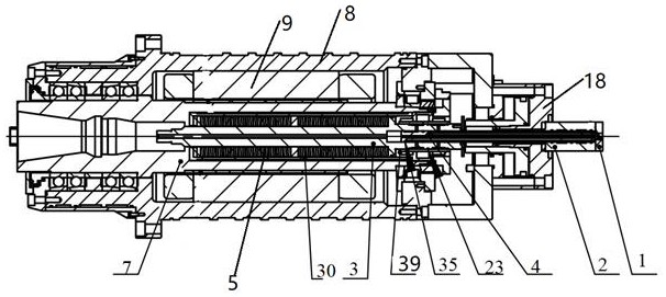
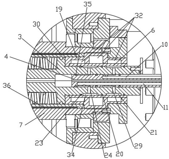
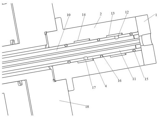
The invention provides a high-power motorized spindle rotor inner heat pipe cooling device for aviation component machining. The high-power motorized spindle rotor inner heat pipe cooling device comprises a broach rod located in a motorized spindle, an inner fluid channel shaft, an annular inner heat pipe body, a pull rod pressing block heat pipe cooling combined body and an inner cooling swivel joint. A sealing cavity is formed between a shaft core and the annular inner heat pipe body, a plurality of capillary grooves are formed in the outer wall of the annular inner heat pipe body and the inner wall of the shaft core in the circumferential direction, the sealing cavity is vacuumized, a low-temperature heat pipe medium is injected into the sealing cavity, and the shaft core and the annular inner heat pipe body form the annular heat pipe. The two ends of the inner fluid channel shaft are arranged in an inner cavity of the inner cooling swivel joint and an inner cavity of the broach rod respectively. The inner cooling swivel joint, the inner fluid channel shaft, the broach rod and the pull rod pressing block heat pipe cooling combined body are all provided with cooling channels, and the inner wall of the pull rod pressing block heat pipe cooling combined body is provided with a cooling groove; and a heat-conducting glue is added between the combined surfaces of the pull rod pressing block heat pipe cooling combined body and the annular inner heat pipe body. According to the invention, stable cooling in the shaft core can be realized.

Description

technical field [0001] The invention belongs to the technical field of aviation component processing, and in particular relates to a high-power electric spindle rotor internal heat pipe cooling device for processing aviation components. Background technique [0002] The machining allowance of the existing aerospace structural parts is particularly large, and the allowance even reaches more than 80% of the material; the power of the spindle is high, the speed is high, the heat generated during the processing is large, and the cutting efficiency is high. Especially for the rare earth permanent magnet synchronous electric spindle, the shaft core and the motor rotor are integrated, and the temperature rise of the rotor will cause the thermal elongation of the spindle and affect the machining accuracy. The existing method of cooling the electric spindle is mainly to cool the stator and bearing of the motor, while the cooling of the rotor is a difficult problem in the industry. ...

Claims


Application Information

Patent Timeline
IPC IPC(8): H02K1/32H02K9/197
CPCH02K1/32H02K9/197
Inventor 范建校徐科王海忠
Owner 西安兴航航空科技股份有限公司
Learn More