
Quantitative salt pot

A pot body and skateboard technology, which can be used in home utensils, applications, kitchen utensils, etc., can solve the problem that the amount of salt added cannot be accurately quantified.

Pending Publication Date: 2021-05-18
李天勇
View PDF0 Cites 0 Cited by
  • Summary
  • Abstract
  • Description
  • Claims
  • Application Information

AI Technical Summary

Problems solved by technology

[0002] Salt is the most commonly used condiment and the most important condiment in the cooking process. The amount of salt added directly affects the taste of dishes, but for non-professional chefs, the amount of salt added cannot be accurately quantified based on experience alone

Method used


Image

  • Quantitative salt pot
  • Quantitative salt pot
  • Quantitative salt pot

Examples


Embodiment 1

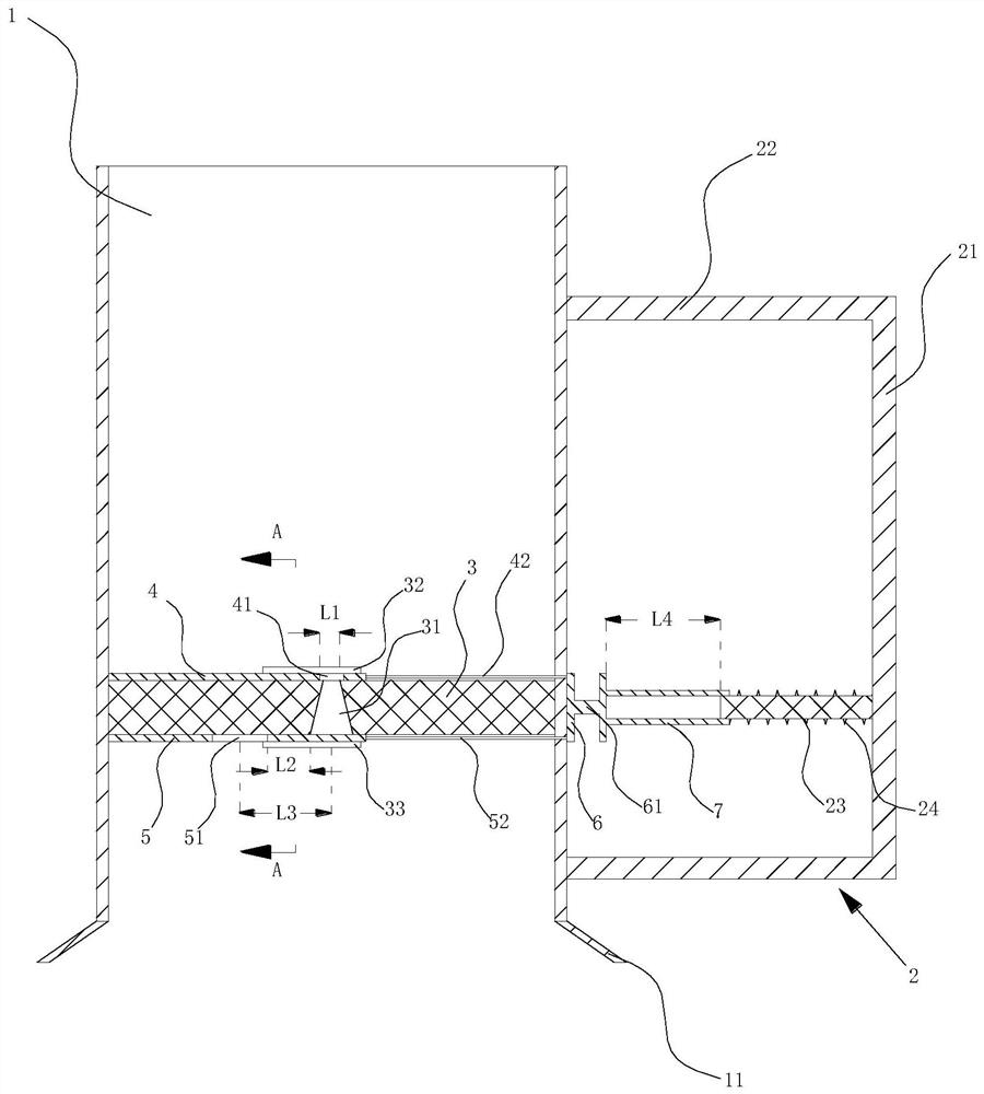
[0027]SeeFigure 1 - Figure 4 Quantitative salt pot, including a vertical arrangement and up and down the cylindrical pot body 1, the mouth of the bottle 1 is provided with a grip 2;

[0028]The lower portion of the pot body 1 is provided with a horizontally arranged partition plate 3, and a tapered through hole 31 having a small diameter of the upper side and a lower diameter of the separator 3;

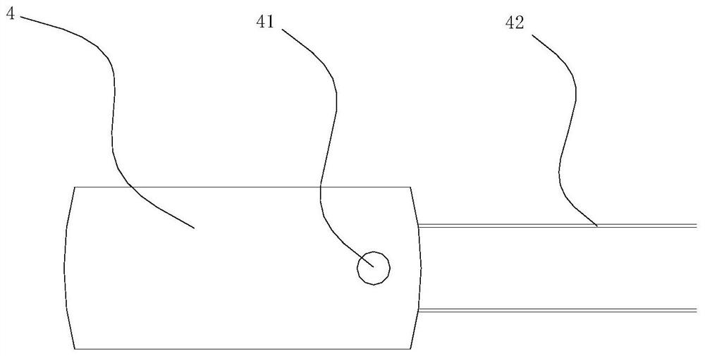
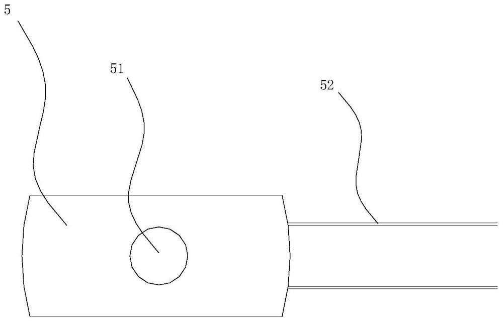
[0029]The upper side of the separator 3 is arranged and left and right-directioned, and the lower side of the first slide 4 is attached to the upper side of the separator 3, and the first slide 4 is sufficient to cover the conical through hole 31, The corresponding tapered through hole 31 is disposed at the corresponding cone 31, and the first through hole 41 is larger than the diameter of the upper opening of the tapered through hole 31, the diameter of the tapered through hole 31. A first guide groove 32 that matches the first sliding plate 4 is provided at the upper position, and the first sl...

Embodiment 2

[0038]SeeFigure 2 - Figure 5Quantitative salt pot, including a vertical arrangement and up and down the cylindrical pot body 1, the mouth of the bottle 1 is provided with a grip 2;

[0039]The lower portion of the pot body 1 is provided with a horizontally arranged partition plate 3, and a tapered through hole 31 having a small diameter of the upper side and a lower diameter of the separator 3;

[0040]The upper side of the separator 3 is arranged and left and right-directioned, and the lower side of the first slide 4 is attached to the upper side of the separator 3, and the first slide 4 is sufficient to cover the conical through hole 31, The corresponding tapered through hole 31 is disposed at the corresponding cone 31, and the first through hole 41 is larger than the diameter of the upper opening of the tapered through hole 31, the diameter of the tapered through hole 31. A first guide groove 32 that matches the first sliding plate 4 is provided at the upper position, and the first sli...


PUM


Abstract

A quantitative salt pot comprises a pot body and a grip. A partition plate is arranged in the kettle body, and a conical through hole is formed in the middle of the partition plate. A first sliding plate is arranged on the upper side of the partition plate, a first through hole is formed in the position, corresponding to the conical through hole, of the first sliding plate, and the right side of the first sliding plate penetrates out of the kettle body through a first push-pull rod. A second sliding plate is arranged on the lower side of the partition plate, a second through hole is formed in the left side, corresponding to the conical through hole, of the second sliding plate, and the right side of the second sliding plate penetrates out of the kettle body through the right side of a second push-pull rod. A connecting plate is arranged on the right side of the kettle body, and the first push-pull rod and the second push-pull rod are connected with the connecting plate. The grip comprises a vertical part and two horizontal parts, a sleeve is arranged on the right side of the connecting plate, a cylinder is arranged on the vertical part, the left part of the cylinder extends into the sleeve, and a self-rebounding device in the left-right direction is arranged between the right side of the sleeve and the vertical part. According to the salt pot, quantitative salt can be added every time, the adding amount is easy to control, errors are extremely small, and use is convenient.

Description

Technical field[0001]The present invention relates to quantitative salt pots.Background technique[0002]Salt is the most commonly used seasoning, and the most important seasoning in the cooking process, the addition of salt directly affects the taste of the dishes, but for non-professional chefs, the addition of salt is only available to accurate quantity with experience.Inventive content[0003]The technical problem to be solved by the present invention is to provide a quantitative salt pot which can add a quantified salt salt, which is easily controlled and the error is extremely small, and is convenient to use.[0004]In order to solve the above technical problems, the present invention provides a quantitative salt pot, including a vertical arrangement and a cylindrical pot body of the upper and lower open, and a grip is provided on the right side of the bottle;[0005]The lower portion of the pot body is provided with a horizontally arranged separator, and the central portion of the pa...

Claims


Application Information

Patent Timeline
IPC IPC(8): A47J47/01A47J47/04
CPCA47J47/01A47J47/04
Inventor 李天勇
Owner 李天勇
Learn More