Stainless steel wire section cutting, winding and drawing machine and operation method

A coiling and drawing machine, stainless steel technology, applied in the field of PLC programmable controllers, can solve the problems of diameter compression deformation, limited steel wire length, scratches, etc.

Inactive Publication Date: 2021-05-18
陈丽娟
View PDF0 Cites 0 Cited by
  • Summary
  • Abstract
  • Description
  • Claims
  • Application Information

AI Technical Summary

Problems solved by technology

[0008] In order to solve the above-mentioned technology, the length of the steel wire is also limited. When it is wound up to the tail end, the steel wire has its own certain hardness. When the tail end does not conflict with the adjustment roller, it will follow the hard force and warp to make it connect and adjust. The mouth will be stretched due to the warping of the steel wire, which will affect its subsequent control range. The diameter of the tail end of the steel wire will be slightly compressed and deformed when it is segmented. The problem of scratching the part where the connecting mouth passes under the force of rolling

Method used


Image

  • Stainless steel wire section cutting, winding and drawing machine and operation method
  • Stainless steel wire section cutting, winding and drawing machine and operation method
  • Stainless steel wire section cutting, winding and drawing machine and operation method

Examples


Embodiment 1

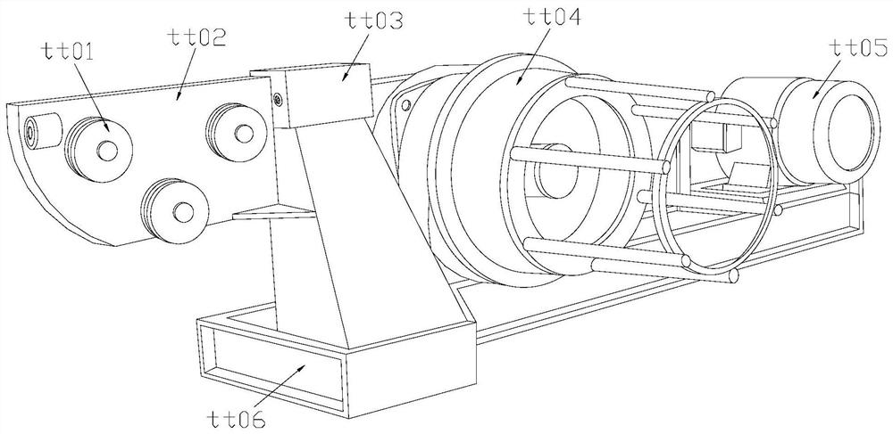
[0031] as attached figure 1 to the attached Figure 5 shown:

[0032] The invention provides a stainless steel wire section winding and drawing machine and an operation method, the structure of which includes an adjustment drawing drum tt01, a side support plate tt02, a connecting and adjusting port tt03, a winding drum tt04, a control end tt05, and a bottom bracket tt06.

[0033] The adjustment pull cylinder tt01 is installed on the outer surface of the side support plate tt02, the side support plate tt02 is welded on the surface of the connecting and adjusting port tt03, the connecting and adjusting port tt03 is connected with the bottom support frame tt06, and the winding drum tt04 is provided. On the side of the control terminal tt05.

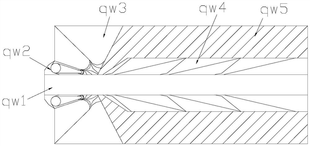
[0034] The connection and adjustment port tt03 includes a hollow port qw1, a constricted edge qw2, a hard corner qw3, a shovel tip qw4, and an outer pocket qw5, the hollow port qw1 is embedded in the outer pocket qw5, and the constricted ...

Embodiment 2

[0041] as attached Image 6 to the attached Figure 7 shown:

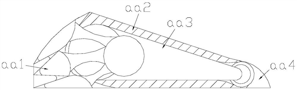
[0042] Wherein, the shovel tip qw4 includes a shovel corner dd01, a spacer dd02, and an anchoring block dd03, the spacer dd02 is connected with the anchoring block dd03, and one end of the spacer dd02 away from the anchoring block dd03 is connected to the shovel The corners dd01 are connected, the anchoring block dd03 is a triangular structure, the spacer dd02 is provided with three, and the shovel corners dd01 allow the outer layer to have a certain hard force to smooth the object protruding from the plane outside, The spacer dd02 makes the connection part more stable when it is stressed.

[0043] Wherein, the shovel edge dd01 includes a push angle vv1, a hard shell vv2, a solid force angle vv3, a rubber edge vv4, and a pressure-releasing ball vv5. The rubber edge vv4 is attached to the outer surface of the pressure-releasing ball vv5. The corner vv3 is embedded in the hard shell vv2, the hard shell vv2 is conn...


PUM


Abstract

The invention discloses a stainless steel wire section cutting, winding and drawing machine and an operation method. The machine structurally comprises an adjusting pull cylinder, a side supporting plate, a connecting adjusting opening and a winding cylinder, the adjusting pull cylinder is installed on the outer surface of the side supporting plate, and a steel wire continuously runs on a track for wire drawing and winding; and when the steel wire is wound to the tail end, the steel wire at the outer end of a hollow opening swings according to the hard force of the steel wire, the steel wire is fixed by a certain force through a stabilizing block, unfolding corners at the two sides bear the extrusion force, the inner part of the steel wire is protected by an outer sticking layer, and the steel wire can be timely pulled to return when the treated tail end of the steel wire tilts, an end opening of the steel wire cannot be pushed to be expanded, the end protruding out of a plane can abut against a shovel edge corner, a force fixing corner fixes hard force on the steel wire, the outer layer has certain hard force to smooth an external object protruding out of the plane, wire drawing can be conducted under the condition that the pressing diameters generated by steel wire section cutting are different, and the part protruding out of the plane can be timely smoothed.

Description

[0001] The application date is December 14, 2019, and the application number is CN201911286867.7. The name of the invention is a divisional application for a stainless steel wire segment coiling and drawing machine. technical field [0002] The invention belongs to the field of PLC programmable controllers, and more specifically relates to a stainless steel wire section winding and drawing machine and an operation method. Background technique [0003] In the process of winding and drawing, the stainless steel rebar needs to be adjusted by several rollers, so that the steel wire passing through it can have the same diameter, and the uneven surface is flattened, stretched, and then rolled together evenly. [0004] Based on the above-mentioned inventor's discovery, the existing wire drawing machine mainly has the following deficiencies, such as: [0005] 1. The length of the steel wire is also limited. When the coil is received at the tail end, the steel wire has a certain hard...

Claims


Application Information

Patent Timeline
Patent Type & Authority Applications(China)
IPC IPC(8): B21C1/02
CPCB21C1/02
Inventor 陈丽娟
Owner 陈丽娟
Why Eureka
Try Eureka