A kind of stainless steel wire section coiling and drawing machine

A technology of winding and drawing machine and stainless steel, applied in the field of PLC programmable controller, can solve the problems of scratches, diameter compression deformation, limited length of steel wire, etc., and achieve the effect of convenient movement and expansion

Active Publication Date: 2021-05-04
赣州大业金属纤维有限公司
View PDF6 Cites 0 Cited by
  • Summary
  • Abstract
  • Description
  • Claims
  • Application Information

AI Technical Summary

Problems solved by technology

[0007] In order to solve the above-mentioned technology, the length of the steel wire is also limited. When it is wound up to the tail end, the steel wire has a certain hardness of its own. When the tail end does not conflict with the adjustment roller, it will follow the hard force and warp to make it connect and adjust. The mouth will be stretched due to the warping of the steel wire, which will affect its subsequent control range. The diameter of the end of the steel wire will be slightly compressed and deformed when it is segmented. The problem of scratching the part where the connecting mouth passes under the force of rolling

Method used


Image

  • A kind of stainless steel wire section coiling and drawing machine
  • A kind of stainless steel wire section coiling and drawing machine
  • A kind of stainless steel wire section coiling and drawing machine

Examples


Embodiment 1

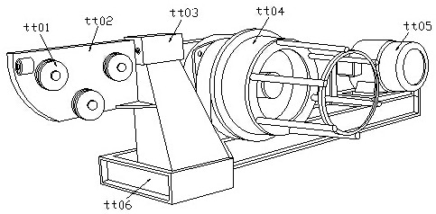
[0030] as attached figure 1 to attach Figure 5 Shown:

[0031] The invention provides a coiling and drawing machine for stainless steel wire sections, the structure of which includes an adjustment pull tube tt01, a side support plate tt02, a joint adjustment port tt03, a retracting tube tt04, a control end tt05, and a bottom support frame tt06.

[0032] The adjustment puller tt01 is installed on the outer surface of the side support plate tt02, the side support plate tt02 is welded to the surface of the joint adjustment port tt03, the joint adjustment port tt03 is connected with the bottom support frame tt06, and the retracting cylinder tt04 is set On the side of the control terminal tt05.

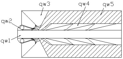
[0033] The connecting mouth tt03 includes a hollow opening qw1, a necking edge qw2, a hard corner qw3, a shovel tip qw4, and an outer pocket shell qw5. The hollow mouth qw1 is embedded in the outer shell qw5, and the necking edge qw2 and The hard angle qw3 is connected, and the shovel ...

Embodiment 2

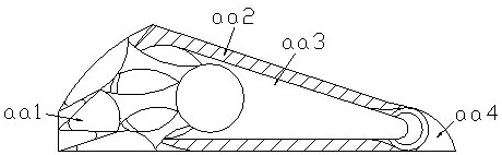
[0040] as attached Image 6 to attach Figure 7Shown:

[0041] Wherein, the shovel tip qw4 includes a shovel edge dd01, a spacer dd02, and an anchor block dd03, the spacer dd02 is connected to the anchor block dd03, and the end of the spacer dd02 far away from the anchor block dd03 is connected to the shovel The corners dd01 are connected, the retaining block dd03 is a triangular structure, the spacer dd02 is provided with three, and the shovel corner dd01 allows the outer layer to have a certain hardness to smooth out objects protruding from the plane outside. The spacer dd02 makes the connecting parts more stable under stress.

[0042] Wherein, the shovel edge angle dd01 includes push angle vv1, hard shell vv2, solid force angle vv3, rubber edge vv4, and pressure-relieving ball vv5, the rubber edge vv4 is attached to the outer surface of the pressure-relieving ball vv5, and the Angle vv3 is embedded inside the hard shell vv2, the hard shell vv2 is connected with the push ...


PUM


Abstract

The invention discloses a coiling and drawing machine for stainless steel wire sections. Its structure includes an adjusting puller, a side support plate, a joint adjustment port, and a retracting barrel. The adjustment pulley is installed on the outer surface of the side support plate, and the steel wire is continuously on the track When the steel wire is rolled to the end, the steel wire at the outer end of the hollow will swing according to its own hardness, and it will be fixed with a certain force by the stable block, and the expansion corners on both sides will bear The force of extrusion is protected by the outer layer. When the tail end of the steel wire is warped, it can be pulled back in time so that it will not push the end of the wire. Expanding, one end of the protruding plane will touch the shovel edge corner, and the solid force angle will fix the hard force on it, so that the outer layer has a certain hard force to smooth the external protruding plane objects, which can be cut by the steel wire When the diameter of the compression produced by the segment is different, the wire is drawn, and the part protruding from the plane is smoothed in time.

Description

technical field [0001] The invention belongs to the field of PLC programmable controllers, and more specifically relates to a stainless steel wire section coiling and drawing machine. Background technique [0002] During the coiling and drawing process of stainless steel bars, it needs to be adjusted by several rollers so that the steel wires passing through them can have the same diameter, and the uneven surface is flattened, straightened and rolled together evenly. [0003] Based on above-mentioned inventor's discovery, existing wire drawing machine mainly has the following deficiencies, such as: [0004] 1. The length of the steel wire is also limited. When it is wound to the end, the steel wire has a certain hardness of its own. When the end does not touch the adjustment roller, it will follow the hard force to warp, so that it will be connected to the adjustment port. Due to the tilting of the steel wire, it is stretched, which affects its subsequent control range. ...

Claims


Application Information

Patent Timeline
Patent Type & Authority Patents(China)
IPC IPC(8): B21C1/02
CPCB21C1/02
Inventor 陈丽娟
Owner 赣州大业金属纤维有限公司
Why Eureka
Try Eureka