Batch flattening and recycling device for zip-top cans

A recycling device, cans technology, applied in the direction of presses, manufacturing tools, etc., can solve the problems of poor extrusion effect, reduced operation volume, and the extrusion environment is not closed.

Pending Publication Date: 2021-05-18
刘学丽
View PDF5 Cites 5 Cited by
  • Summary
  • Abstract
  • Description
  • Claims
  • Application Information

AI Technical Summary

Problems solved by technology

[0004] In order to overcome the shortcomings of relying on manual pushing and collecting of cans, the distance between the cans and the extruder is relatively close, there are potential safety hazards, and the extrusion environment is not clos...

Method used


Image

  • Batch flattening and recycling device for zip-top cans
  • Batch flattening and recycling device for zip-top cans
  • Batch flattening and recycling device for zip-top cans

Examples


Embodiment 1

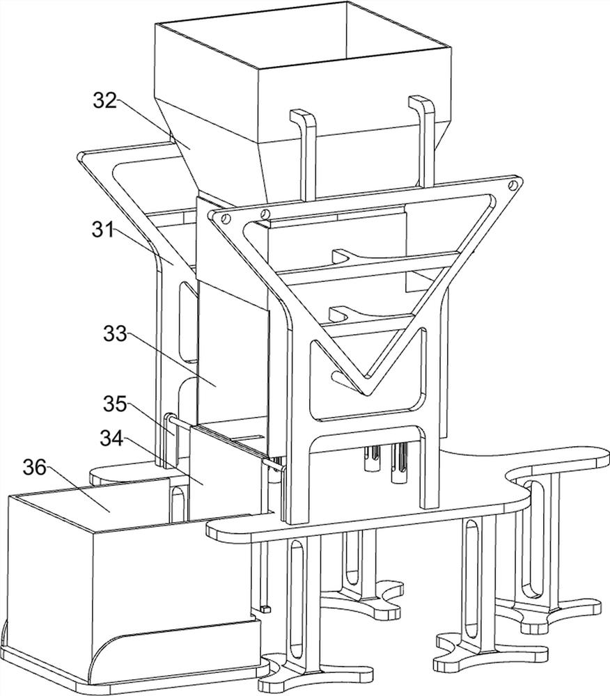
[0055] A batch flattening recovery device for pop cans, such as figure 1 As shown, it includes a base 1, a bottom plate 2, a can flow mechanism 3 and a flattening mechanism 4, which is provided with a base 1 and a bottom plate 2, the bottom plate 2 is located on the left side of the base 1, and the top of the base 1 and the bottom plate 2 is connected with a can flow direction Mechanism 3, the top right side of the base 1 is provided with a flattening mechanism 4.

[0056] The staff can place the cans in the cans flow mechanism 3, start the operation of the flattening mechanism 4 to flatten the cans, after the flattening is completed, the cans can be collected, and after all the flattening is completed, stop the operation of the flattening mechanism 4.

Embodiment 2

[0058] On the basis of Example 1, such as figure 2 and image 3As shown, the can flow direction mechanism 3 includes a support frame 31, a feed frame 32, a working chamber 33, a baffle plate 34, a support seat 35 and a material storage frame 36. The top of the base 1 is symmetrically provided with a support frame 31, and the top of the support frame 31 A feed frame 32 is connected between them, a working chamber 33 is connected between the middle parts of the support frame 31, a support seat 35 is arranged symmetrically on the left side of the top of the base 1, and a baffle plate 34 is rotatably connected between the top of the support seat 35, and the baffle plate 34 and The working cavity 33 is engaged, and the top of the bottom plate 2 is provided with a material storage frame 36 .

[0059] Flattening mechanism 4 includes mounting seat 41, cylinder 42, telescopic push rod 43, pressing plate 44, connecting column 45 and buffer spring 46, base 1 top right side is provided ...

Embodiment 3

[0062] On the basis of Example 2, such as Figure 4 to Figure 7 As shown, it also includes an automatic switch mechanism 5 for the material retaining plate. The automatic switch mechanism 5 for the material retaining plate includes a connecting rod 51, a first rack 52, a first transmission gear 53 and a movable guide frame 54. On the telescopic rod of the cylinder 42 Connecting rod 51 is connected, and base 1 top front side is provided with movable guide frame 54, and movable guide frame 54 is connected with connecting rod 51 slidingly, and the left side of connecting rod 51 is connected with first rack 52, and on the rotating shaft of baffle plate 34 A first transmission gear 53 is connected, and the first transmission gear 53 meshes with the first rack 52 .

[0063] The expansion rod of the cylinder 42 drives the first rack 52 to move to the left through the connecting rod 51, and the first rack 52 moves to the left through the first transmission gear 53 to drive the baffle ...


PUM


Abstract

The invention relates to a flattening and recycling device, in particular to a batch flattening and recycling device for zip-top cans. The invention mainly aims to provide a batch flattening and recycling device for zip-top cans, which provides a closed extrusion environment, carries out automatic blanking, pushing and extrusion through a machine, reduces the operation amount and ensures the safety. The batch flattening and recycling device for the zip-top cans comprises a base, a zip-top can flow direction mechanism and a flattening mechanism, wherein the base and a bottom plate are arranged; the zip-top can flow direction mechanism is connected between the base and the top of the bottom plate; and the flattening mechanism is arranged at one side of the top of the base. Through the arrangement of the zip-top can flow direction mechanism and a baffle locking mechanism, when a baffle is clamped with a working cavity, a buckle is driven to clamp the baffle, so that the situation that the baffle is pushed away by too large force of a flattening plate, and the working process is affected is prevented; and through the arrangement of the flattening mechanism, the flattening plate is driven to move leftwards to flatten the zip-top cans, so that the basic functions of the device are achieved.

Description

technical field [0001] The invention relates to a flattening recovery device, in particular to a batch flattening recovery device for pop cans. Background technique [0002] Pop cans, that is, the material of the can lid itself is processed to form a rivet, and a pull ring is riveted on the outer jacket, and a complete can lid is formed with a corresponding score. The can is light in weight, small in size, not easy to break, It is easy to carry, so it is favored by people. Most of the materials used to make cans are aluminum. Environmentalists believe that aluminum cans are more environmentally friendly than other packaging containers. As far as their containers are concerned, repeated recycling reduces environmental pollution. In terms of the materials used, the repeated use of aluminum is effective and can save resources and maintain the earth's environment. [0003] After the cans are recycled, they will be flattened. Generally, the staff needs to push the collected cans...

Claims


Application Information

Patent Timeline
IPC IPC(8): B30B9/32B30B15/30B30B15/32
CPCB30B9/321B30B15/30B30B15/32
Inventor 刘学丽
Owner 刘学丽
Why Eureka
Try Eureka