Energy storage device

An energy storage device and packaged technology, applied in the field of solar power generation, can solve problems such as easy accumulation or adhesion of impurities in the energy storage device, affecting the energy storage effect of the energy storage device, and heat loss of the heat storage device

Pending Publication Date: 2021-05-18
STATE GRID HEBEI ELECTRIC POWER RES INST +2
View PDF7 Cites 2 Cited by
  • Summary
  • Abstract
  • Description
  • Claims
  • Application Information

AI Technical Summary

Problems solved by technology

[0003] The purpose of the present invention is to provide an energy storage device, aiming to solve the problem that impurities are easy to accumulate or adhere to the inner wall of the energy storage device in the prior art, which affects the energy storage effect of the energy storage device, and the phase change material is heated by a heater to store heat. The device is prone to heat transfer with the outside world resulting in heat loss

Method used


Image

  • Energy storage device
  • Energy storage device
  • Energy storage device

Examples


Embodiment Construction

[0044] In order to make the technical problems, technical solutions and beneficial effects to be solved by the present invention clearer, the present invention will be further described in detail below in conjunction with the accompanying drawings and embodiments. It should be understood that the specific embodiments described here are only used to explain the present invention, not to limit the present invention.

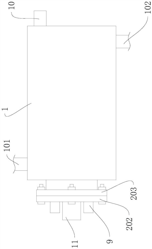
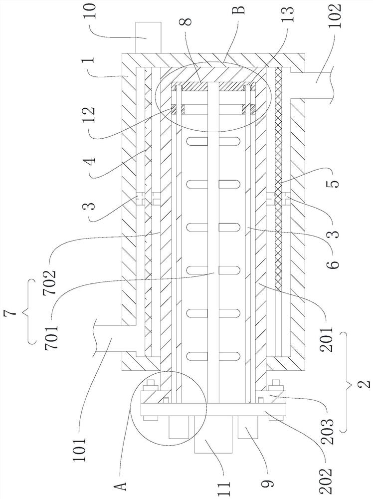
[0045] Please also refer to figure 1 and figure 2 , the energy storage device provided by the present invention will now be described. The energy storage device includes an inner tank 2, an outer tank 1, a first lead screw 6, a first scraper 12 and a first motor 9, the inner tank 2 is used to store phase change materials; the outer tank 1 is set outside the inner tank 2, The outer tank 1 is used to accommodate the heating medium, and the outer tank 1 is respectively provided with a liquid inlet 102 and a liquid outlet 101; the first screw 6 is rotated in the inn...


PUM


Abstract

The invention provides an energy storage device, and belongs to the technical field of solar power generation. The energy storage device comprises an inner tank, an outer tank, a first lead screw, a first motor and a first scraper; the inner tank is used for storing a phase change material; the inner tank is sleeved with the outer tank, the outer tank is connected with the inner tank in a sealed mode, the outer tank is used for containing a heating medium, and a liquid inlet and a liquid outlet are arranged on the outer tank respectively; the first lead screw is rotatably arranged in the inner tank; the first motor is arranged outside the inner tank and is connected with the first lead screw; and the first scraper is in threaded connection with the first lead screw, moves in the axial direction of the first lead screw and is used for cleaning the phase change material adhered to the inner wall of the inner tank. According to the energy storage device provided by the invention, the problems that the energy storage effect of the energy storage device is affected due to the fact that impurities are easily accumulated or adhered to the inner wall of the energy storage device in the prior art, and heat loss is caused due to the fact that the phase change material is heated through a heater and a heat storage device is easily subjected to heat transfer with the outside are solved.

Description

technical field [0001] The invention belongs to the technical field of solar power generation, and more specifically relates to an energy storage device. Background technique [0002] At present, most of the concentrating photovoltaic heat storage and cascade heat systems use combined phase change materials for phase change energy storage. Phase change energy storage technology uses phase change energy storage or gasification) to achieve energy storage by releasing and absorbing heat during the process. The phase change material is stored in the energy storage device. By heating the energy storage device, the phase change material stores the absorbed heat energy, but the phase change material is easy to accumulate on the inner wall of the energy storage device, resulting in poor energy storage efficiency. The existing energy storage device heats the phase change material through a heater, so that the energy storage device can easily transfer heat with the outside, resulting...

Claims


Application Information

Patent Timeline
IPC IPC(8): F28D20/02F28G1/08
CPCF28D20/02F28G1/08Y02E60/14
Inventor 周文苏灿曾四鸣臧谦李铁成杨鹏杨少波孟良
Owner STATE GRID HEBEI ELECTRIC POWER RES INST
Why Eureka
Try Eureka