
Optical sensor module and electronic equipment

A technology of optical sensors and electronic equipment, applied in the field of optics, can solve the problems of reducing the accuracy of target parameters and different signal-to-noise ratios

Pending Publication Date: 2021-05-18
BEIJING XIAOMI MOBILE SOFTWARE CO LTD
View PDF4 Cites 0 Cited by
  • Summary
  • Abstract
  • Description
  • Claims
  • Application Information

AI Technical Summary

Problems solved by technology

During the assembly of electronic equipment, limited by the installation process of the optical sensor module, there will be work differences in the installation position in the x direction and the z direction, which will cause changes in the photosensitive area and photosensitive angle, resulting in the perception of photodiodes in different electronic devices. The signal-to-noise ratio of the optical signal is different, thereby reducing the accuracy of the target parameters

Method used


Image

  • Optical sensor module and electronic equipment
  • Optical sensor module and electronic equipment
  • Optical sensor module and electronic equipment

Examples


Embodiment Construction

[0046] Reference will now be made in detail to the exemplary embodiments, examples of which are illustrated in the accompanying drawings. When the following description refers to the accompanying drawings, the same numerals in different drawings refer to the same or similar elements unless otherwise indicated. The implementations described in the following exemplary examples do not represent all implementations consistent with the present disclosure. Rather, they are merely examples of devices consistent with aspects of the present disclosure as recited in the appended claims.

[0047] At present, the optical sensor module in the electronic device is provided with a photodiode, which can convert the light signal transmitted through the display screen of the electronic device into an electrical signal, and is an important optical sensing device in the optical sensor module.

[0048] With the development of electronic equipment to full screen, the area where holes can be opened...


PUM


Abstract

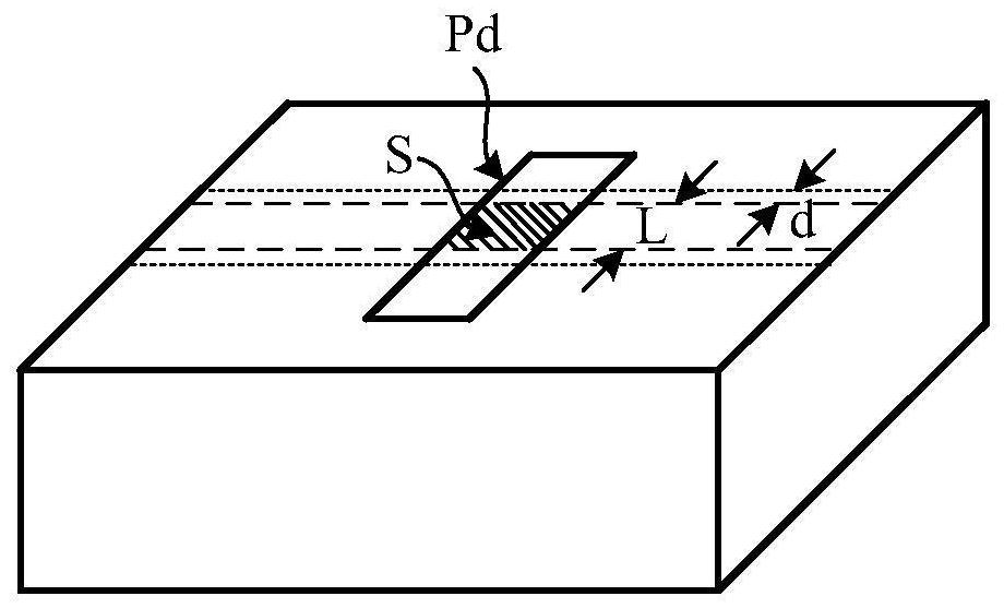
The invention relates to an optical sensor module and electronic equipment. The electronic equipment comprises an optical sensor module and a display screen, an optical window is arranged on the display screen; the optical sensor module comprises a photoelectric sensing device; the length of the photoelectric sensing device in the set direction exceeds a preset length threshold value; and the set direction refers to the direction perpendicular to the optical windowing center line. According to the embodiment of the invention, the length of the photoelectric sensing device in the set direction is set to exceed the preset length threshold value; wherein the set direction refers to the direction perpendicular to the center line of the optical window, so that no matter how the optical sensor module is assembled, the overlapping area of the photoelectric sensing device and the optical window is always unchanged, and the area of the overlapping area does not change along with the installation difference, thereby ensuring that the signal-to-noise ratio of an optical signal sensed by the photoelectric sensing device is basically unchanged; and the accuracy of subsequently obtaining the target parameters can be ensured.

Description

technical field [0001] The present disclosure relates to the field of optical technology, in particular to an optical sensor module and electronic equipment. Background technique [0002] At present, the optical sensor module in the electronic device is provided with a photodiode, which can convert the light signal transmitted through the display screen of the electronic device into an electrical signal, and is an important optical sensing device in the optical sensor module. [0003] With the development of electronic equipment to full screen, the area where holes can be opened on the display screen is getting smaller and smaller. Therefore, the existing electronic equipment adopts a narrow slit solution to set the receiving hole for the optical sensor module, but the length of the receiving hole is very small. For example, the narrowest point in the x-direction of the electronic device is about 0.3mm. [0004] In practical applications, when a photodiode senses a light si...

Claims


Application Information

Patent Timeline
Patent Type & Authority Applications(China)
IPC IPC(8): G01J1/02G01J1/04G09F9/00
CPCG01J1/02G01J1/0407G09F9/00
Inventor 陈朝喜
Owner BEIJING XIAOMI MOBILE SOFTWARE CO LTD
Learn More