Hoisting device for rapid lifting of pressure chamber of true triaxial testing machine

A hoisting device and pressure chamber technology, which is applied in the field of hoisting devices for rapid lifting of the pressure chamber of a true triaxial testing machine, can solve problems affecting the measurement accuracy of sensors on the assembly, potential safety hazards, and low service life

Pending Publication Date: 2021-05-18
BACKFILL ENG LAB SHANDONG GOLD MINING TECH CO LTD +1
View PDF0 Cites 1 Cited by
  • Summary
  • Abstract
  • Description
  • Claims
  • Application Information

AI Technical Summary

Problems solved by technology

[0003] However, the existing hoisting devices for rapid lifting of the pressure chamber generally have the following problems: ①. Only one hoisting pipe is used to connect the pressure chamber, and the pressure chamber is prone to swing during the lifting process, which can easily cause the pressure chamber wall and The collision of the rock sample assembly will affect the measurement accuracy of the sensor on the assembly at the slightest, and may directly lead to the scrapping of the rock sample assembly at the worst; ②. Since the weight of the pressure chamber can reach about one ton, after long-term frequent During the lifting operation, the lifting pipe has the problem of fatigue deformation, resulting in a low service life; ③, the pressure chamber and the lifting pipe need to be connected by bolts, and the pressure chamber needs to be disassembled and assembled after each lifting operation. It is laborious and laborious, and there are certain security risks

Method used


Image

  • Hoisting device for rapid lifting of pressure chamber of true triaxial testing machine
  • Hoisting device for rapid lifting of pressure chamber of true triaxial testing machine
  • Hoisting device for rapid lifting of pressure chamber of true triaxial testing machine

Examples


Embodiment Construction

[0015] The present invention will be further described in detail below in conjunction with the accompanying drawings and specific embodiments.

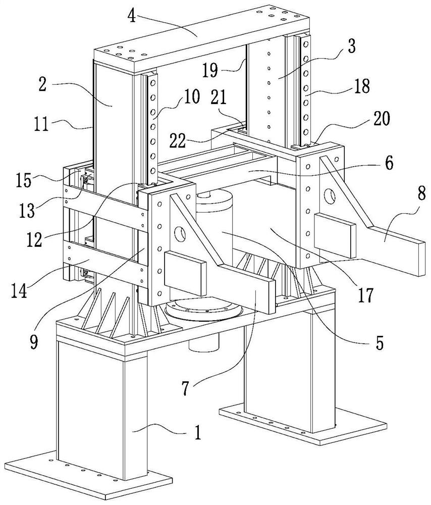
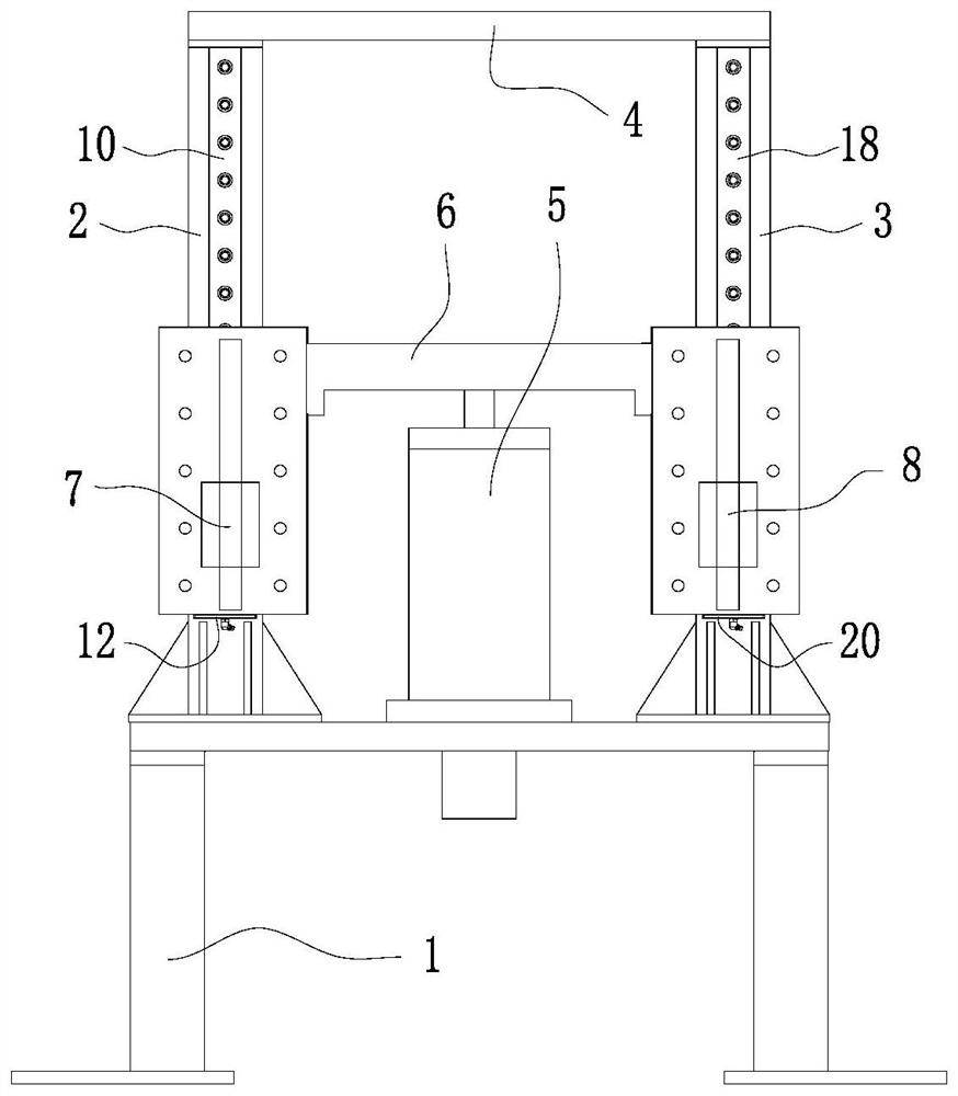
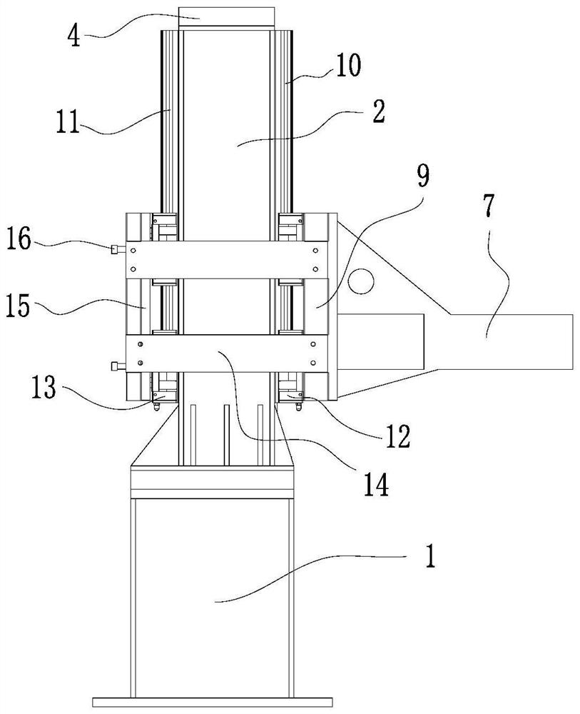
[0016] like Figure 1~4 As shown, a hoisting device for rapid lifting of the pressure chamber of a true triaxial testing machine, including a base 1, a first column 2, a second column 3, a beam 4, a lifting hydraulic cylinder 5, a lifting beam 6, a first lifting Guide assembly, the second lifting guide assembly, the first lifting arm 7 and the second lifting arm 8; the first column 2 and the second column 3 are vertically fixed on the top of the base 1, the first column 2 and the second column The tops of the two columns 3 are fixedly connected by a beam 4; the lifting hydraulic cylinder 5 is vertically fixed on the top of the base 1 with the piston rod facing upwards, and the lifting hydraulic cylinder 5 is located in the middle of the first column 2 and the second column 3 The lifting beam 6 is horizontally fixed on the top of the ...


PUM


Abstract

The invention discloses a hoisting device for rapidly lifting of a pressure chamber of a true triaxial testing machine. Two stand columns are vertically and fixedly arranged at the top of a base, and the top ends of the two stand columns are fixedly connected through a cross beam; a lifting hydraulic cylinder is vertically and fixedly installed on the top of the base, a piston rod is arranged upwards, and the lifting hydraulic cylinder is located in the middle of the two stand columns; a lifting beam is horizontally and fixedly arranged at the top end of the piston rod of the lifting hydraulic cylinder, one end of the lifting beam is connected with the first stand column through a first lifting guide assembly, and the other end is connected with the second stand column through a second lifting guide assembly; a first lifting support arm is mounted on the first lifting guide assembly and synchronously moves along with the lifting beam; a second lifting support arm is mounted on the second lifting guide assembly and synchronously moves along with the lifting beam; a first support arm insertion lifting lug and a second support arm insertion lifting lug are respectively mounted on the pressure chamber, and the two support arm insertion lifting lugs are in one-to-one correspondence with the two lifting support arms in position; and the first lifting support arm is matched with the first support arm insertion lifting lug in an insertion mode, and the second lifting support arm is matched with the second support arm insertion lifting lug in an insertion mode.

Description

technical field [0001] The invention belongs to the technical field of rock mechanics tests, in particular to a hoisting device for rapid lifting of a pressure chamber of a true triaxial testing machine. Background technique [0002] At present, in the existing true triaxial testing machine, for the pressure chamber adopting the upper and lower opening structure, it is necessary to cooperate with the lifting operation of the pressure chamber during the disassembly and assembly of the sample, and the lifting of the pressure chamber requires a hoisting device. Finish. [0003] However, the existing hoisting devices for rapid lifting of the pressure chamber generally have the following problems: ①. Only one hoisting pipe is used to connect the pressure chamber, and the pressure chamber is prone to swing during the lifting process, which can easily cause the pressure chamber wall and The collision of the rock sample assembly will affect the measurement accuracy of the sensor on...

Claims


Application Information

Patent Timeline
Patent Type & Authority Applications(China)
IPC IPC(8): G01N3/02G01N3/12
CPCG01N3/02G01N3/12G01N2203/0019G01N2203/0048G01N2203/0256
Inventor 刘洋王剑波刘焕新张希巍李桂林侯奎奎尹延天王玺张皓钦
Owner BACKFILL ENG LAB SHANDONG GOLD MINING TECH CO LTD
Why Eureka
Try Eureka