
Digital pumping unit control cabinet driven by switched reluctance motor

A technology of switched reluctance motor and pumping unit, applied in the field of control cabinet, can solve problems such as unfavorable use, unfavorable positioning and installation of control box, adjustment of installation position, etc.

Pending Publication Date: 2021-05-18
山东汇久石油装备有限公司
View PDF0 Cites 0 Cited by
  • Summary
  • Abstract
  • Description
  • Claims
  • Application Information

AI Technical Summary

Problems solved by technology

[0003] However, most of the existing control cabinet structures are simple cabinets, with a layer of cabinet doors directly hinged on the surface, which is not conducive to the stable positioning and installation of the internal control box, and the installation position cannot be adjusted according to the size of the control box, which is easy to cause loosening. At the same time, touch the buttons directly during operation, which cannot be isolated and protected, and is easily disturbed by pollution, which is not conducive to use and needs to be improved.

Method used


Image

  • Digital pumping unit control cabinet driven by switched reluctance motor
  • Digital pumping unit control cabinet driven by switched reluctance motor
  • Digital pumping unit control cabinet driven by switched reluctance motor

Examples


Embodiment Construction

[0027] The following will clearly and completely describe the technical solutions in the embodiments of the present invention in conjunction with the accompanying drawings in the embodiments of the present invention; obviously, the described embodiments are only part of the embodiments of the present invention, not all embodiments, based on The embodiments of the present invention and all other embodiments obtained by persons of ordinary skill in the art without making creative efforts belong to the protection scope of the present invention.

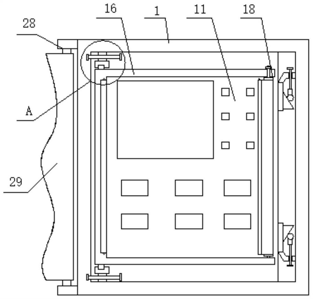
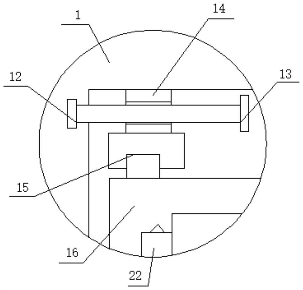
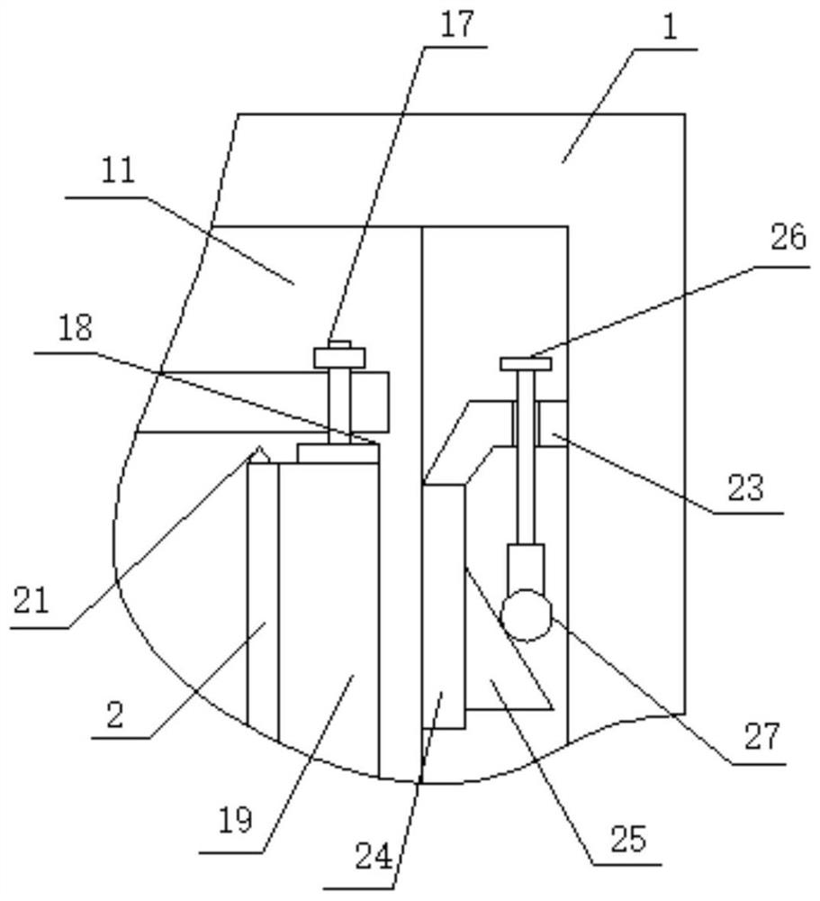
[0028] see Figure 1-3 , a switched reluctance motor-driven digital pumping unit control cabinet, including cabinet 1, please refer to figure 1 with figure 2 A control box 11 is fixedly installed on one side surface of the cabinet body 1, which can be connected to the circuit for operation control. There is an adjustment threaded rod 13, and the surface of the adjustment threaded rod 13 is threadedly connected with an adjustment nut 1...


PUM


Abstract

The invention discloses a digital pumping unit control cabinet driven by a switched reluctance motor. The digital pumping unit control cabinet comprises a cabinet body, a control box is fixedly installed on the surface of one side of the cabinet body, and rotating blocks are rotationally connected to the two ends of the surface at one side of the cabinet body. Adjusting threaded rods are rotationally installed on the side faces of the rotating blocks, the surface of the adjusting threaded rod is in threaded connection with an adjusting nut, and the surface at one end of the adjusting nut is slidably connected to the side faces at the two ends of the cabinet body; a hinge base is arranged on the surface at the other end of the adjusting nut, a U-shaped connecting rod is hinged to the surface of the hinge base, and the U-shaped connecting rod is located at one side of the control box. Threaded shafts are rotationally installed at the two ends of the U-shaped connecting rod correspondingly, a winding rod is fixedly connected to one end of each threaded shaft, the two ends of each winding rod are rotationally connected to the surfaces at the two ends of the U-shaped connecting rod, and a silica gel protective film is fixedly wound around the surface of each winding rod, so that use convenience and stability can be greatly improved, and safety is guaranteed.

Description

technical field [0001] The invention relates to the field of control cabinets, in particular to a digital pumping unit control cabinet driven by a switched reluctance motor. Background technique [0002] During the operation and use of the digital pumping unit, the digital control box is generally used for switch control, and for safety protection and easy management, it needs to be installed inside the control cabinet. [0003] However, most of the existing control cabinet structures are simple cabinets, with a layer of cabinet doors directly hinged on the surface, which is not conducive to the stable positioning and installation of the internal control box, and the installation position cannot be adjusted according to the size of the control box, which is easy to cause loosening. At the same time, touch the buttons directly during operation, which cannot be isolated and protected, and is easily disturbed by pollution, which is not conducive to use and needs to be improved....

Claims


Application Information

Patent Timeline
Patent Type & Authority Applications(China)
IPC IPC(8): H05K5/02H05K7/14
CPCH05K5/02H05K5/0217H05K7/1401
Inventor 巴洪梅齐书杰张力杰
Owner 山东汇久石油装备有限公司
Learn More