Vehicle control device
A vehicle control device and vehicle technology, applied to vehicle components, transportation and packaging, steering mechanisms, etc., can solve problems such as driver incoordination
- Summary
- Abstract
- Description
- Claims
- Application Information
AI Technical Summary
Problems solved by technology
Method used
Image

Examples
Embodiment 1
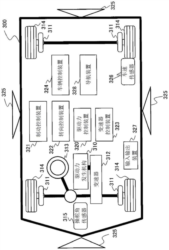
[0046]figure 1 In order to show the configuration of a vehicle including the vehicle control device 324 in the first embodiment of the present invention.
[0047]The vehicle 300 includes a driving force generating mechanism 310, a brake 311, and a transmission 312, the driving force generating mechanism 310, powered by a power source, the brake 311 brakes the vehicle, and the transmission 312 has a driving force in the appropriate direction. 310 The driving force generated by the vehicle is advanced or retracted. The output of the transmission 312 causes the left and right wheels 314 to rotate the vehicle 300, and the vehicle 300 is generated by controlling the brake 311 to decelerate the vehicle 300.
[0048]The driving force generating mechanism 310 can be a hybrid mechanism of an engine or an engine and a motor, or a motor monomer. The vehicle 300 has a steering wheel 313, and the steering angle of the wheel 314 is changed by operating the steering wheel 313, and the vehicle 300 turns....
Embodiment 2
[0165]Embodiment 2 illustrates an example of the setting processing of the driver's operational intervention information 450 of the step 505 shown in the first embodiment.Figure 12 A flowchart of an example of setting processing representing a driving intervention area based on the driver's operation intervention information. This processing instead of the Example 1Figure 6 Execute it.Figure 13 A top view of an example of the set travel path. Furthermore, other configurations are the same as those of the first embodiment.
[0166]Figure 12 In step S801, the path generation unit 403 selects into a change target based on the position and angle of the vehicle 300, which has occurred the intervention of the driver's driving operation, and the travel direction before the driver's operation involved. The line segment of the travel area 104.
[0167]In step S802, as in the first embodiment, the path generation unit 403 sets the predetermined distance R (radius R) from each vehicle end point 704....
Embodiment 3
[0183]Embodiment 3 illustrates an example of the setting process of the driver's operational intervention information 450 of the step 505 shown in the first embodiment.Figure 14 A flowchart of an example of setting processing representing a driving intervention area based on the driver's operation intervention information. This processing instead of the Example 1Figure 6 Execute it.Figure 15 A top view of an example of the set travel path. The processing of steps S801 to S804 and the Example 1Figure 6 the same. Furthermore, other configurations are the same as those of the first embodiment.
[0184]The path generating unit 403 can determine whether or not the driver's operational intervention information 450 is replaced according to the comparison of the state information of the vehicle in the automatic parking history information 460 described in the automatic parking history information 460, as described in the first embodiment. set. In other words, the path generating unit 403 chang...
PUM
 Abstract
Description
Claims
Application Information