Hardware product clamping auxiliary punching equipment

A technology of punching equipment and products, applied in metal processing equipment, drilling/drilling equipment, clamping and other directions, can solve the problems of pressing the drill bit laboriously, hardware products cannot stop moving instantaneously, etc., to avoid position deviation. Effect

Active Publication Date: 2021-05-25
崇义县佰盛五金制品有限公司
View PDF5 Cites 3 Cited by
  • Summary
  • Abstract
  • Description
  • Claims
  • Application Information

AI Technical Summary

Problems solved by technology

[0005] In order to overcome the shortcomings in the prior art that the hardware products cannot be clamped and fixed, the hardware products cannot stop moving instantaneously, and it is laborious to press down on the drill bit, the technical problem is: to provide a convenient way to adjust the position of the hardware products and punch holes for them, and easily clamp them horizontally and vertically Fixed hardware products, which can control the hardware products to stop moving instantly, and facilitate the clamping of the hardware products that press down the drill bit. Auxiliary drilling equipment

Method used


Image

  • Hardware product clamping auxiliary punching equipment
  • Hardware product clamping auxiliary punching equipment
  • Hardware product clamping auxiliary punching equipment

Examples


Embodiment 1

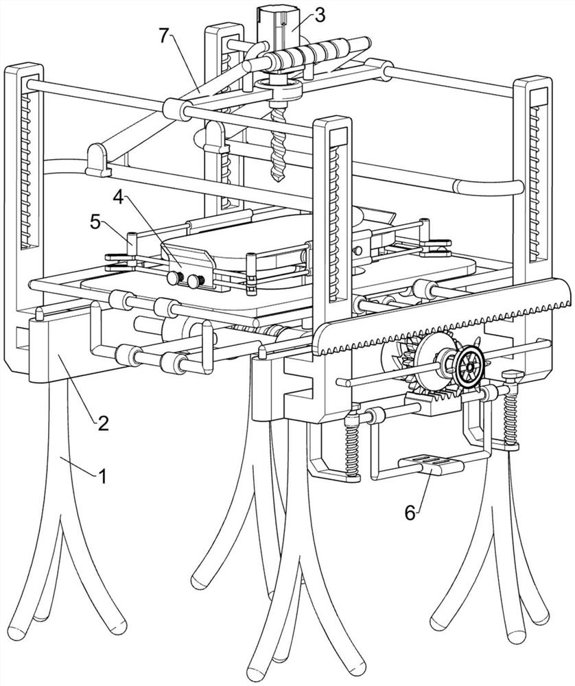
[0024] A punching device assisted by clamping of hardware products, such as figure 1 , figure 2 and image 3 As shown, it includes a supporting foot 1, a moving mechanism 2 and a punching mechanism 3. The supporting feet 1 are symmetrically arranged on the front and rear sides on the ground, and the moving mechanism 2 is arranged between the upper parts of the supporting feet 1. Punch mechanism3.

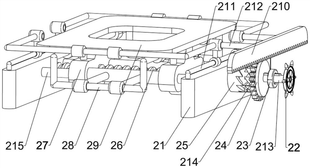
[0025] Moving mechanism 2 comprises base 21, hand wheel 22, supporting shaft frame 23, clutch block 24, transmission block 25, screw mandrel 26, position-limiting seat 27, first sliding seat 28, placing platform 29, rack 210, the first Two sliding seats 211 and a connecting frame 212, a base 21 is connected between the support feet 1 on the front and rear sides, and a support shaft frame 23 is connected between the left and right sides of the front side base 21, and the support shaft frame 23 is internally rotatable and The rotating shaft 213 is slidingly connected, the front si...

Embodiment 2

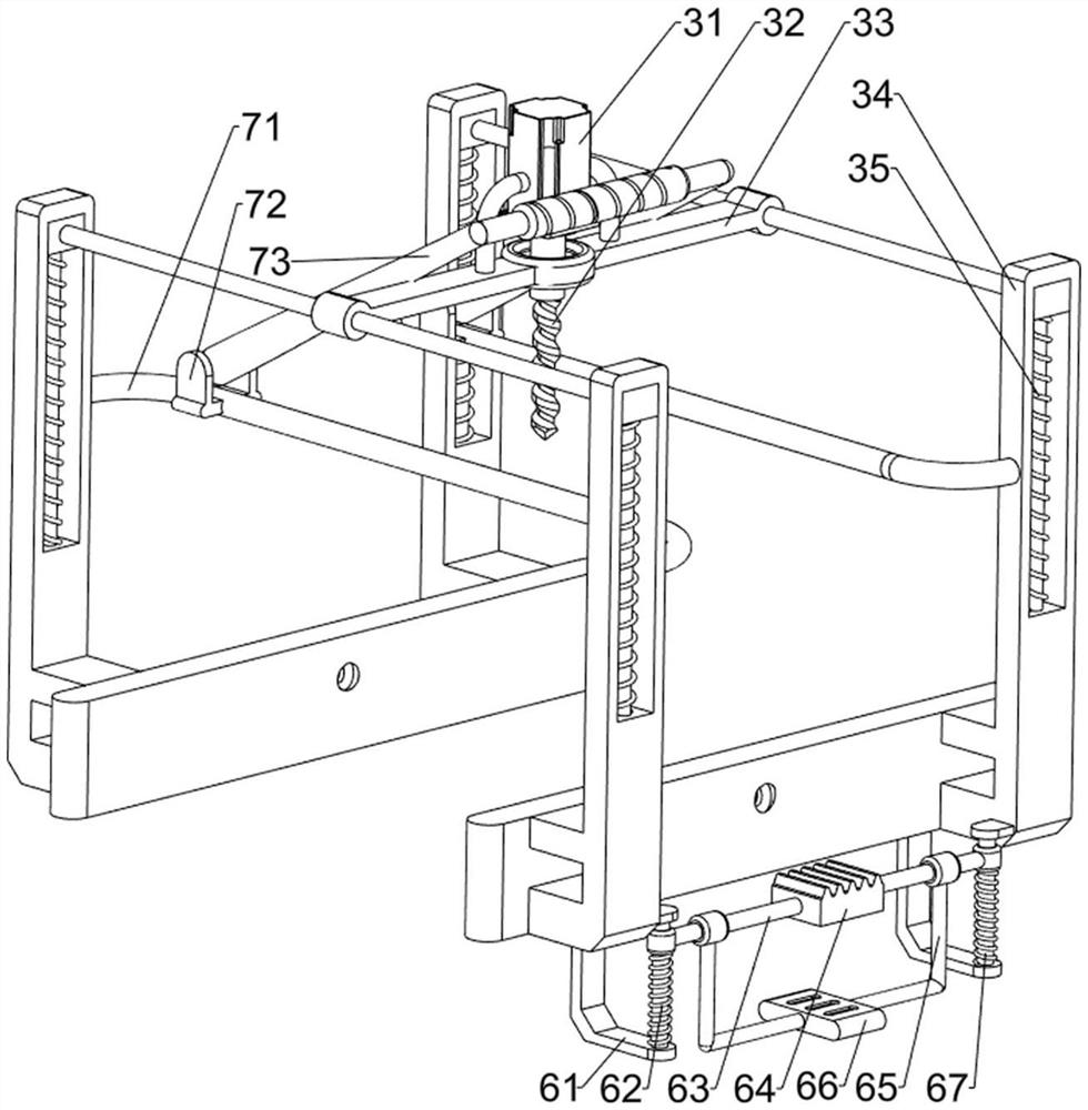
[0029] On the basis of Example 1, such as figure 1 , image 3 and Figure 4 Shown, also include lateral clamping assembly 4, lateral clamping assembly 4 includes stand 41, second guide bar 42, second spring 43, arc plate 44, long rod 45 and groove block 46, place platform 29 The left and right sides of the upper part are all connected with a stand 41, and the outside of the stand 41 is connected with a second guide rod 42 symmetrically before and after, and an arc-shaped plate 44 is slidably connected between the second guide rod 42, and the arc-shaped plate 44 is connected with the second guide rod 42. A second spring 43 is connected between the outer sides of the guide rods 42, and the second spring 43 is sleeved on the second guide rod 42. The front and rear sides of the arc plate 44 are connected with long rods 45 symmetrically up and down. Between all are connected with groove block 46.

[0030] Also includes a longitudinal clamping assembly 5, the longitudinal clampin...


PUM


Abstract

The invention relates to punching equipment, in particular to hardware product clamping auxiliary punching equipment. According to the hardware product clamping auxiliary punching equipment provided by the invention, the position of a hardware product can be conveniently adjusted, the hardware product is punched, the hardware product is easily clamped and fixed in the transverse direction and the longitudinal direction, the hardware product can be controlled to stop moving instantly, and a drill bit can be conveniently pressed down. The hardware product clamping auxiliary punching equipment comprises supporting legs, a moving mechanism and a punching mechanism, wherein the supporting legs are symmetrically arranged on the two sides of the ground; the moving mechanism is arranged between the upper parts of the supporting legs; and the punching mechanism is arranged on the moving mechanism. According to the hardware product clamping auxiliary punching equipment provided by the invention, by pushing the hardware product to move downwards and pushing an arc-shaped plate to move towards the outer side, a groove frame, a connecting plate and a pressing plate are pushed to move towards the inner side through a groove block, and the pressing plate moves towards the outer side after making contact with the hardware product, so that the effect of conveniently clamping and fixing the hardware product in the transverse direction and the longitudinal direction is achieved, and position deviation of the hardware product is avoided.

Description

technical field [0001] The invention relates to a punching device, in particular to a punching device for clamping auxiliary hardware products. Background technique [0002] In the field of production and construction, hardware products are a very common material. In order to make better use of hardware products, sometimes it is necessary to punch holes for hardware products according to requirements. [0003] The existing punching equipment for hardware products mainly moves the hardware products back and forth, left and right, to a suitable position, and then presses down on the drill bit to punch holes. During the hole process, the hardware product may shift and affect the drilling. Secondly, when the hardware product is pushed to move, due to the action of inertia, etc., the hardware product may stop moving to the correct position instantaneously, and the position of the punching hole will deviate. Finally Pressing down on the drill bit to drill holes consumes more phys...

Claims


Application Information

Patent Timeline
Patent Type & Authority Applications(China)
IPC IPC(8): B23B47/00B23Q3/06B23Q5/10B23Q5/22B23B47/18B23B47/06
CPCB23B47/00B23Q3/06B23Q5/22B23Q5/10
Inventor 罗键
Owner 崇义县佰盛五金制品有限公司
Why Eureka
Try Eureka