A welding method of an ultrasonic welding machine

A welding method and ultrasonic technology, applied in welding equipment, non-electric welding equipment, metal processing equipment, etc., can solve the problems of prolonged cylinder action time, large stroke distance, and crushed parts to be welded, so as to improve welding efficiency and ensure welding. quality effect

Active Publication Date: 2022-06-28
SBT ULTRASONIC TECH CO LTD
View PDF6 Cites 0 Cited by
  • Summary
  • Abstract
  • Description
  • Claims
  • Application Information

AI Technical Summary

Problems solved by technology

[0002] Ultrasonic welding machine is a device that converts electrical energy into mechanical energy. By making the welding head vibrate at high frequency, the contact head of the welding head will rub against the workpiece to generate the heat required for welding to complete the welding of the workpiece; in ultrasonic welding In the process, sometimes in order to avoid fixtures or auxiliary structures, the stroke distance between the welding head and the welding seat will be relatively large. Therefore, the cylinder on the existing ultrasonic welding machine will push the welding head down to the position of the welding seat to complete the welding operation , as the stroke of the cylinder becomes longer, the action time of the cylinder is lengthened, which affects the working efficiency of the ultrasonic welding machine; in order to shorten the time of pressing the welding head, those skilled in the art have designed a welding head and welding seat that can move at the same time However, the ultrasonic welding machine that can move the welding head and the welding seat at the same time cannot strictly control the order of the welding head and the welding seat, so the welding head may reach the welding position before the welding seat and crush Therefore, this type of machine has to use the welding seat to move to the support position under the workpiece before welding, and then the welding head moves down to the top of the workpiece for welding. Only after welding, it can move back at the same time. to the initial position

Method used


Image

  • A welding method of an ultrasonic welding machine
  • A welding method of an ultrasonic welding machine

Examples


Embodiment 1

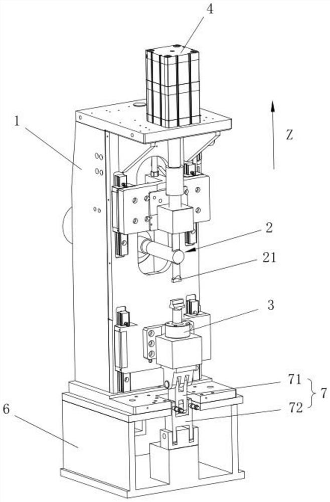
[0039] This embodiment provides an ultrasonic welding machine, such as figure 1 As shown, the ultrasonic welding machine includes a frame 1, a triple group 2, a first drive assembly, a welding seat 3 and a second drive assembly, the triple group 2 includes a welding head 21, and the triple group 2 is movably arranged on the frame 1, and The triplet 2 can move along the Z direction; the first drive assembly is connected to the triplet 2 through a transmission to drive the triplet 2 to move along the Z direction, and the first drive assembly can drive the triplet 2 to move to the preset position and the first working position; The welding seat 3 is movably arranged on the frame 1, and the welding seat 3 can move in the Z direction. The second driving component is connected with the welding seat 3 to drive the welding seat 3 to move in the Z direction, and the second driving component can drive the welding seat. 3 Move to the second working position; when the first drive assembly...

Embodiment 2

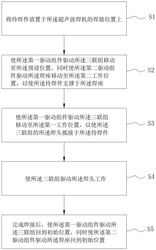
[0047] This embodiment provides a welding method for an ultrasonic welding machine, and the welding method uses the ultrasonic welding machine in the first embodiment to perform welding operations, such as figure 2 As shown, the welding method includes the steps:

[0048] S1. Place the parts to be welded on the welding position of the ultrasonic welding machine;

[0049] S2. Make the first drive assembly drive the triplet 2 to move to a preset position, and while driving the triplet 2 to move, make the second drive assembly drive the welding seat 3 to move to the second working position, so that the workpiece to be welded is supported on the welding seat 3;

[0050] S3, make the first drive assembly drive the triple group 2 to move to the first working position, so that the welding head 21 of the triple group 2 is in contact with the workpiece to be welded;

[0051] S4, make the triple group 2 drive the welding head 21 to work, so that the welding head 21 performs the weldi...


PUM


Abstract

The invention belongs to the technical field of ultrasonic welding machines, and discloses a welding method for ultrasonic welding machines. The welding method uses a multi-position cylinder set on the ultrasonic welding machine to drive the triple group to move along the Z direction, so as to realize the step-by-step pressing down of the welding head , to prevent that when the welding head and the welding seat move to the working position at the same time, because the welding head and the welding seat cannot strictly control the sequence of reaching the working position, it may happen that the welding head first moves to the working position while the welding seat has not yet reached the supporting position , causing the parts to be welded to be crushed, this welding method significantly improves the efficiency on the premise of ensuring the welding quality.

Description

technical field [0001] The invention relates to the technical field of ultrasonic welding machines, in particular to a welding method of an ultrasonic welding machine. Background technique [0002] Ultrasonic welding machine is a device that converts electrical energy into mechanical energy. By making the welding head vibrate at high frequency, the contact head of the welding head is rubbed with the workpiece, and the heat required for welding is generated to complete the welding of the workpiece; in the ultrasonic welding process In the process, sometimes in order to avoid the fixture or auxiliary structure, the travel distance between the welding head and the welding seat will be relatively large. Therefore, the cylinder on the existing ultrasonic welding machine will push the welding head to the welding seat position to complete the welding operation. , due to the longer stroke of the cylinder, the action time of the cylinder is prolonged, which in turn affects the workin...

Claims


Application Information

Patent Timeline
Patent Type & Authority Patents(China)
IPC IPC(8): B23K20/10B23K20/26
CPCB23K20/10B23K20/26
Inventor 周宏建石新华
Owner SBT ULTRASONIC TECH CO LTD
Why Eureka
Try Eureka