Tire

A tire, tire circumferential technology, applied in tire parts, tire tread/tread pattern, transportation and packaging, etc., to improve snow removal, improve driving performance, and inhibit the reduction of rigidity

Pending Publication Date: 2021-05-25
SUMITOMO RUBBER IND LTD
View PDF19 Cites 0 Cited by
  • Summary
  • Abstract
  • Description
  • Claims
  • Application Information

AI Technical Summary

Problems solved by technology

[0004] In the pneumatic tire of Patent Document 1 mentioned above, there is room for research to improve the driving performance and wear resistance on low-μ roads such as iron-plated roads with a small friction coefficient, and snowy roads in a balanced manner.

Method used


Image

  • Tire
  • Tire
  • Tire

Examples


Embodiment Construction

[0032] Hereinafter, one embodiment of the present invention will be described based on the drawings.

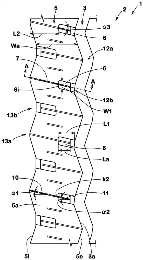
[0033] figure 1 It is an expanded view of the tread portion 2 of the tire 1 according to the present embodiment. As a preferred method, figure 1 An all-season pneumatic tire 1 mounted on a light truck is shown. In addition, the present invention can also be applied to a pneumatic tire 1 for cars or trucks, or tires 1 in other categories.

[0034] like figure 1 As shown, the tread portion 2 of the present embodiment includes a longitudinal groove 3 extending in the tire circumferential direction and a land portion 5 adjacent to the longitudinal groove 3 .

[0035] In the present embodiment, the land portion 5 is divided by a first circumferential edge 5e on the side of the longitudinal groove 3 and a second circumferential edge 5i on the opposite side to the first circumferential edge 5e. The first circumferential edge 5e is, for example, an intersection edge where the tr...


PUM


Abstract

According to the invention, the driving performance and the wear resistance on a low mu road and a snow road are improved in a balanced manner. A tire (1) has a tread portion (2). The tread portion (2) includes a longitudinal groove (3) and a land portion (5). The land portion (5) is provided with a first lateral groove (6) and a sipe (7). The first lateral groove (6) extends in the tire axial direction from the first circumferential edge (5e) and has an inner end (6i) interrupted within the land portion (5). A tie bar (8) is provided on the inner end (6i) side of the first transverse groove (6) at a length smaller than the length (L1) of the first transverse groove (6). The sipe (7) includes a first sipe portion (10) extending from the second circumferential edge (5i) toward the first lateral groove (6), and a second sipe portion (11) extending on the tie bar (8).

Description

technical field [0001] The present invention relates to tires. Background technique [0002] Patent Document 1 described below describes a pneumatic tire having an intermediate rib defined by a center side circumferential groove and a shoulder side circumferential groove. The middle rib is provided with an inclined long groove opening to the shoulder-side circumferential groove, and an inclined sipe communicating with the inclined long groove and extending to the center-side circumferential groove. [0003] Patent Document 1: Japanese Unexamined Patent Publication No. 2013-151235 [0004] In the pneumatic tire of Patent Document 1 mentioned above, there is room for study to improve the driving performance and wear resistance performance on low-μ roads such as iron-plated roads and snowy roads with a small friction coefficient in a balanced manner. Contents of the invention [0005] The present invention has been made in view of the above actual situation, and its main ob...

Claims


Application Information

Patent Timeline
Patent Type & Authority Applications(China)
IPC IPC(8): B60C11/03
CPCB60C11/03B60C11/032B60C11/0327B60C11/0306B60C2011/0346B60C2011/0344B60C2011/0381B60C2011/0369B60C11/125B60C2011/1209B60C11/1369B60C2011/0367B60C11/1259
Inventor 门司真美
Owner SUMITOMO RUBBER IND LTD
Why Eureka
Try Eureka